Team Leader(s)
Abbigale Smith, Nickolas Heysler, Kenny Hibbard, Garrett Ho, Ian Leon, Simona Vileniskyte
Team Member(s)
Quang Dinh, Tatiana Forbes, Nickolas Heysler, Kenny Hibbard, Garrett Ho, James House, Kailyn Lake, Ian Leon, Abbigale Smith, Simona Vileniskyte, Trenton Wright
Faculty Advisor
Dr. Douglas Willard, Dept. of Aerospace Engineering, Florida Tech
Mobile Engine Testing Application (META) Test Stand File Download
Project Summary
The Mobile Engine Testing Application (META) Test Stand is capable of test-firing solid and liquid bipropellant rocket engines. This continuation project from the 2021-2022 META team required plumbing, structures, safety, and procedures modifications to support the liquid fuel, oxidizer, and cooling system. META Test Stand collaborated with META Controls and META Engines senior design teams to meet the objectives. META offered universal testing capabilities to customer teams like BiPROP and Aerospike. META shall be used for customers, STEM education outreach, and an astronautics-focused lab at Florida Tech.
Project Objective
OBJ-01 META Test Stand shall integrate a liquid bipropellant rocket and subsequent DAQ systems.
OBJ-02 The team shall deliver an integration, user, and safety procedures manual.
OBJ-03 The team shall design and integrate a pump, reservoir and plumbing network for an engine cooling system.
OBJ-04 The team shall revise the gas piping installation and conduct a maintenance check on the blast wall.
OBJ-05 The team shall mount three 1000 lbf low profile universal or compression pancake load cells and additional sensors to the thrust structure.
OBJ-06 The team shall fire the integrated liquid bipropellant rocket, cooling system, and control to validate test systems.
Manufacturing Design Methods
Plumbing:
• The plumbing system, constructed by the 2021-2022 META team, has been modified and upgraded to comply with the objectives set for the current META team. For example, a closed-loop Cooling System was installed to cool liquid propellant rocket engines. The closed-loop cooling system allows testing to be done in remote locations. Per the plumbing requirements, all system components were limited and chosen by the operating temperature and space allocated.
Structures:
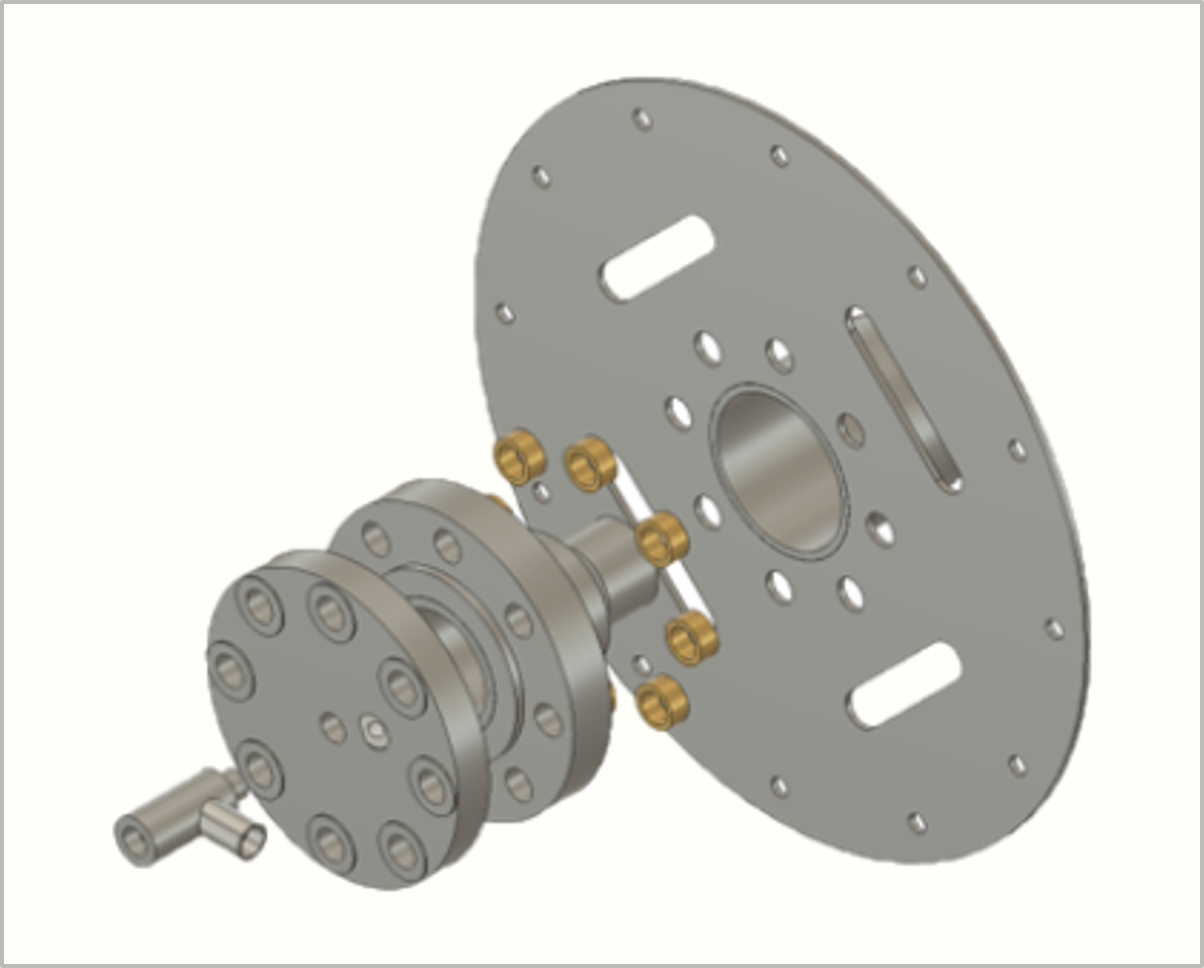
• The flushing tank containers needed redesigning. This involved new brackets for stabilization, new frames and connectors, new top and bottom plate for greater structural quality, and bracket, bottom, and top plate fabrication. A new pump mount was needed, and to generate one, this included verifying designs and materials through simulation (ANSYS), ordering the suitable material, and manufacturing the mount before installation.
• For a new safety box with mountings, various design simulations were taken into account. This included using ANSYS and hand calculations to determine the structural load the box needed to hold and the stress it could withstand. Once this process was done, a structurally stable box and mounting brackets needed to be ordered and installed. Some minor components also needed were offset bars to screw onto the test stand for the brackets to rest on and rubber sheets to screw in between the bars and brackets to prevent unwanted vibrations.
• Fuel and oxidizer load cells were needed, and the sizing and location information would be taken from the META controls team. These design components would allow the structures team to determine what material to order, where to manufacture the cells, and how to install them properly.
• A new cooling pump bracket was taken into consideration. This bracket also needed to run through design verifications using ANSYS and hand calculations. Once this was done, the proper material was ordered, and the bracket was manufactured prior to installation.
Specification
• Test plans are used to provide a written testing guideline to ensure safe and smooth operations. They include the main objectives of the test, the test’s procedure, as well as assigned roles for the procedure. Communication procedures were created and added after the first test to avoid confusion with information and the walkie talkies used.
• Safety procedures, hazards, and emergency contacts are listed on test plans to reduce the risk of injury to any team members. These hazards and risks are mentioned in a mandatory safety meeting prior to any testing, to ensure all personnel attending tests are aware of what to do in case of an emergency.
• The testing location was determined based off the Florida State Motor Class Requirements listed below. The largest motor to be tested this year is an L Class motor, meaning a clearance radius of 300 feet is to be given around the test stand in every direction. With this information, the Compound in Palm Bay, Florida was chosen as a testing location.
Analysis
The META Test Stand team successfully worked with and accommodated customers while integrating new ideas with other META teams. A new piping system was developed and utilized for the hydrostatic testing of a liquid bi-propellent tank. Hand calculations and a water flow test were conducted to verify the plumbing and analyze the system's mass flow rate. Hand calculations and ANSYS stress and strain analysis demonstrated all CAD-modeled structural elements' load capabilities.
Future Works
While the team successfully used and adapted the test stand to accommodate customer teams' testing, a liquid bipropellant test fire was not conducted. In the future, a liquid bipropellant test fire can be done to verify the test stand's plumbing and structure, as well as the integrated controls and rocket engine.
Manufacturing Design Methods
Plumbing:
• The plumbing system, constructed by the 2021-2022 META team, has been modified and upgraded to comply with the objectives set for the current META team. For example, a closed-loop Cooling System was installed to cool liquid propellant rocket engines. The closed-loop cooling system allows testing to be done in remote locations. Per the plumbing requirements, all system components were limited and chosen by the operating temperature and space allocated.
Structures:
• The flushing tank containers needed redesigning. This involved new brackets for stabilization, new frames and connectors, new top and bottom plate for greater structural quality, and bracket, bottom, and top plate fabrication. A new pump mount was needed, and to generate one, this included verifying designs and materials through simulation (ANSYS), ordering the suitable material, and manufacturing the mount before installation.
• For a new safety box with mountings, various design simulations were taken into account. This included using ANSYS and hand calculations to determine the structural load the box needed to hold and the stress it could withstand. Once this process was done, a structurally stable box and mounting brackets needed to be ordered and installed. Some minor components also needed were offset bars to screw onto the test stand for the brackets to rest on and rubber sheets to screw in between the bars and brackets to prevent unwanted vibrations.
• Fuel and oxidizer load cells were needed, and the sizing and location information would be taken from the META controls team. These design components would allow the structures team to determine what material to order, where to manufacture the cells, and how to install them properly.
• A new cooling pump bracket was taken into consideration. This bracket also needed to run through design verifications using ANSYS and hand calculations. Once this was done, the proper material was ordered, and the bracket was manufactured prior to installation.
![]()


.png)
