Project Summary
The Automated Drone Navigation project aims to mitigate the risks to public safety associated with the loss of communication between the aircraft AW609 and the command center. Through proper implementation of the SOAR cognitive architecture, we plan to develop an intelligent agent that can assume control of the AW609 during emergencies and navigate it back to its origin or destination safely, while avoiding densely populated areas. The project will also include a graphical user interface (GUI) for monitoring critical data such as fuel levels, airspeed, elevation, and altitude in real-time, as well as a map that tracks the aircraft's location and the path generated by the intelligent agent. Through these developments, the project seeks to ensure the safety of the public by having the agent navigate the AW609 around densely populated areas with minimized risk.
Project Objective
Project Objective:
The objective of this project is to mitigate the potential risks associated with operating the AW609 by
implementing an automated system that permits the agent to assume control in situations where
communication with the control tower is lost. By leveraging the SOAR cognitive architecture to design an
intelligent agent capable of flying the aircraft to its intended destination or returning to the starting point
during emergencies, we can guarantee the safety of the flight.
Manufacturing Design Methods
Design:
The system must be integrated with the SOAR architecture; a cognitive agent which performs decisions to pilot
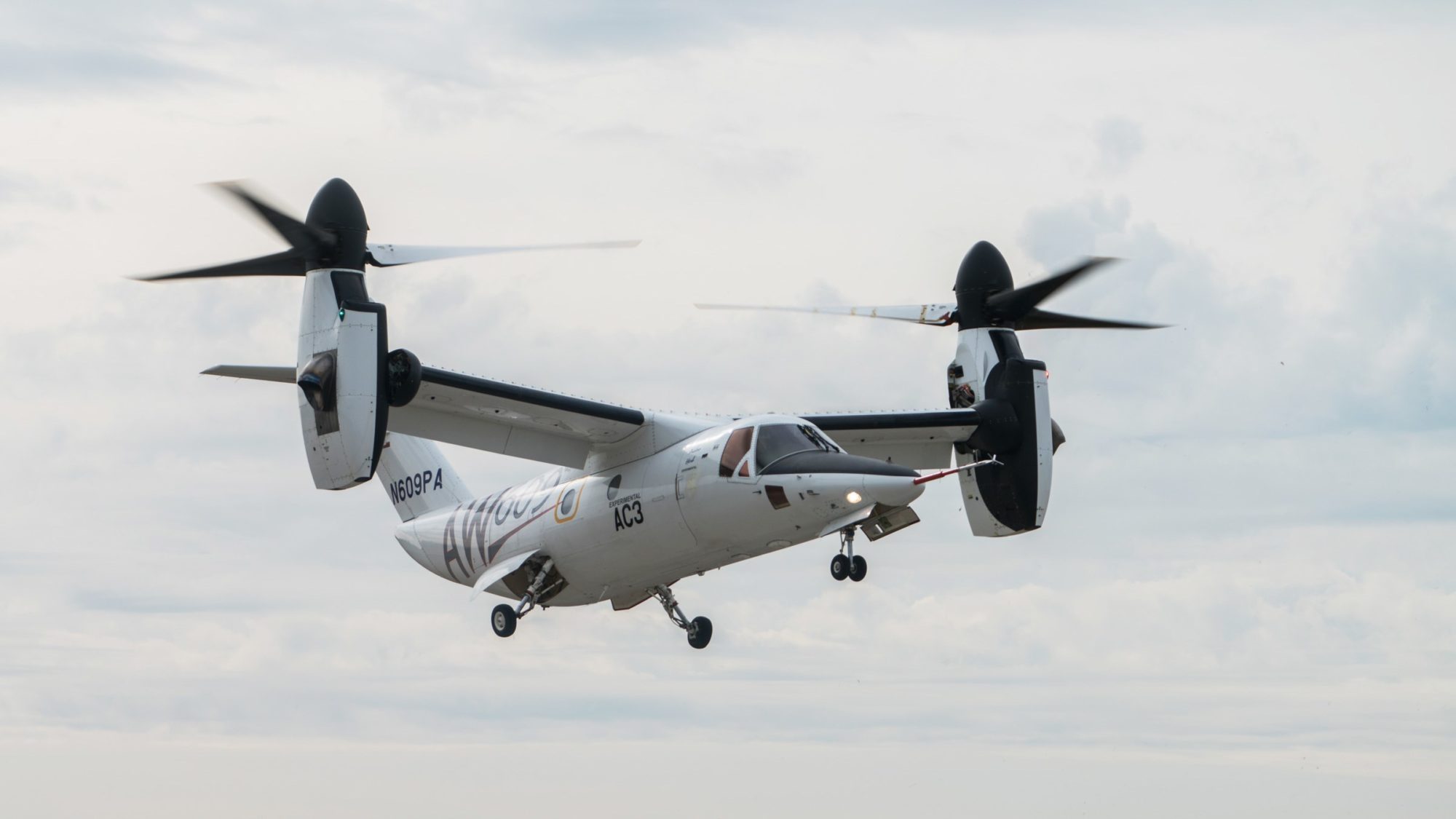
the aircraft in the XPlane 11 simulator. The aircraft under focus to be operated by the SOAR agent is the
Agustawestland's AW609, which has a unique capability to takeoff/land vertically similarly to a helicopter and
fly horizontally as a typical aircraft. This SOAR agent would be able to determine whether it must navigate, and
land safety following proper FAA (Federal Aviation Agency) protocol. The SOAR agent would decide on the
safest course of action to return back to its starting location or continue safely to its destination while avoid densely populated areas.
Architecture challenges:
The SOAR cognitive architecture, when implemented appropriately, is a general intelligent agent capable of
performing tasks, learning, making decisions, solving problems, and planning based on information provided to
it. This architecture is based on a platform that was quite novel to our team's methodology and took some time
to get used to, as it requires proposals of certain rules that, when met, must be paired with a follow-on event
execution. These proposals and events must then be chained in sequence to ensure the aircraft performs as
expected. However, this required a lot of fine-tuning because the SOAR agent will always execute if the given
conditions are met, even if the situation is not suited for that action, resulting in a paradigm shift in our team's
thinking to perform countless system tests and make adjustments to the architecture. We were ultimately
successful in creating an environment where the agent went from a 10% success rate in landings to 90%.
Implementation Challenges:
Upon activation of the loss of communication the SOAR agent would assume control of the aircraft and determine its current position relative to its initial position and compare it with a determined distance resulting from the pathfinding algorithm. The constraints of distance and fuel must be taken into account. The novelty of this project is the SOAR cognitive architecture deciding on the most appropriate course of action and fine tuning the algorithm has proven to be incredibly difficult. This implementation has caused us to revise our approach 3 separate times ultimately resulting in an amalgamation of Dijkstra and the on board AI system industrial aircrafts utilize. Previous attempts considered locations in the sparse regions of the map to have nodes and boundary nodes around densely populated areas shaping into an irregular polygon. The difficulty proved to be navigating as efficiently as possible without additional travel time and exceeding fuel constraints. The speed in which the Agent would have to determine which nodes to travers proved extensively difficult as each node required n^n total edges where n is the number of nodes. This proved to be incredibly overwhelming and as the aircraft was constantly moving, SOAR agent could not make a decisive decision in the short time it had. Our implementation ultimately created the environment where the autopilot would head toward the closest entry node to a polygon and perform Djikstra to traverse around the node and creating a forwarding future position of the aircraft incrementally spaced out, the SOAR agent is able to determine where to exit the polygon without all polygons to be connected to each other in a graph, ultimately reducing processing time to O(n).
Analysis
Analysis:
Multiple tests were conducted to evaluate the decision-making capabilities of the agent in situations where
communication is lost. Specifically, we developed numerous scenarios in which the aircraft was situated in
densely populated areas following the loss of communication. The SOAR agent was expected to recognize the
issue, identify the most efficient and direct flight path to escape the congested area and reach the intended
destination, and proceed along that path until the destination was reached. Additionally, various other testing
procedures were employed, including the placement of the aircraft in random locations and environmental
conditions, to verify the agent's capacity to successfully initiate takeoff, operate the aircraft safely, and land it at
the intended destination.
Future Works
Future Works:
Potential future developments for this project encompass incorporating machine learning to better predict path based on previous flight data, adding weather factors that may affect flight, and refining the SOAR architecture to improve the agent's decision-making process. Additionally, the optimization of the algorithm for flying around dense regions can be further enhanced to efficiently plot a course towards its destination.
Other Information
However, it is important to note that all the testing were done in a simulated environment and do not account for the complexities of the actual aircraft, which would require further development and implementation.
Manufacturing Design Methods
Design:
The system must be integrated with the SOAR architecture; a cognitive agent which performs decisions to pilot
the aircraft in the XPlane 11 simulator. The aircraft under focus to be operated by the SOAR agent is the
Agustawestland's AW609, which has a unique capability to takeoff/land vertically similarly to a helicopter and
fly horizontally as a typical aircraft. This SOAR agent would be able to determine whether it must navigate, and
land safety following proper FAA (Federal Aviation Agency) protocol. The SOAR agent would decide on the
safest course of action to return back to its starting location or continue safely to its destination while avoid densely populated areas.
Architecture challenges:
The SOAR cognitive architecture, when implemented appropriately, is a general intelligent agent capable of
performing tasks, learning, making decisions, solving problems, and planning based on information provided to
it. This architecture is based on a platform that was quite novel to our team's methodology and took some time
to get used to, as it requires proposals of certain rules that, when met, must be paired with a follow-on event
execution. These proposals and events must then be chained in sequence to ensure the aircraft performs as
expected. However, this required a lot of fine-tuning because the SOAR agent will always execute if the given
conditions are met, even if the situation is not suited for that action, resulting in a paradigm shift in our team's
thinking to perform countless system tests and make adjustments to the architecture. We were ultimately
successful in creating an environment where the agent went from a 10% success rate in landings to 90%.
Implementation Challenges:
Upon activation of the loss of communication the SOAR agent would assume control of the aircraft and determine its current position relative to its initial position and compare it with a determined distance resulting from the pathfinding algorithm. The constraints of distance and fuel must be taken into account. The novelty of this project is the SOAR cognitive architecture deciding on the most appropriate course of action and fine tuning the algorithm has proven to be incredibly difficult. This implementation has caused us to revise our approach 3 separate times ultimately resulting in an amalgamation of Dijkstra and the on board AI system industrial aircrafts utilize. Previous attempts considered locations in the sparse regions of the map to have nodes and boundary nodes around densely populated areas shaping into an irregular polygon. The difficulty proved to be navigating as efficiently as possible without additional travel time and exceeding fuel constraints. The speed in which the Agent would have to determine which nodes to travers proved extensively difficult as each node required n^n total edges where n is the number of nodes. This proved to be incredibly overwhelming and as the aircraft was constantly moving, SOAR agent could not make a decisive decision in the short time it had. Our implementation ultimately created the environment where the autopilot would head toward the closest entry node to a polygon and perform Djikstra to traverse around the node and creating a forwarding future position of the aircraft incrementally spaced out, the SOAR agent is able to determine where to exit the polygon without all polygons to be connected to each other in a graph, ultimately reducing processing time to O(n).
![]()


.jpg)