Mission

The mission of the mechanical and civil engineering department is to prepare graduate and undergraduate students to be successful professionals and leaders in global and local environments related to the workplace in industry, research, business, and management.

Civil Engineering and Construction Management

Plastic Recycling Plant


Team Leader(s)
Eric Davidson

Team Memeber(s)
Eric Davidson, Alaina Pistininzi, Kaelen Childers, Stephan Heinrichs, JayZe Elysee

Faculty Advisor
Troy Nguyen

Secondary Faculty Advisor
Albert Bleakley


Plastic Recycling Plant  File Download
Project Summary
The recycling plant measures 52,000 square feet. Most of this space is dedicated to the processing, packing, and storing of plastic waste. The facility also has office spaces to manage the facility and its workers/machines and lab spaces to test the incoming and outgoing materials. The design is based off very large machines that required a large amount of space, power, and water to function. Although the team could have settled for one of each machine for a smaller facility, building a large industrial-grade facility would make better use of the parcel of land chosen. Designing the building with extra room allows for the potential to expand/develop without the need to rebuild. The building uses a steel frame with prefabricated exterior walls to protect the machines from the outside. A metal roof allows the easy installation of solar panels.


Project Ojective
Design a recycling plant using sustainable processes to minimize the production of construction-related waste.

Manufacturing Design Methods
The parcel of land chosen for the project is located in a flood zone. The site has to be elevated by at least five feet, meaning a lot of dirt would need to be brought in on top of the removal of mucky topsoil. New utility lines are also required, for the land is surrounded by I-95 and private property owners. Designing a roadway that was big enough for trucks but small enough to fit on the property was a challenge, and several different designs were considered.

Specification
52,000 sq ft. Metal Roof set at 15 degree angle with 6" overhangs. Height: 43 feet. 6" Concrete Foundation Retention Pond 150' by 300' 5' x 5' Footings 480 Volt, 3-phase power system Several separate HVAC Units sized for each area 4 Bathrooms, including one shower area

Analysis
The high costs of land, earthwork, and new utility lines drive the cost of the building. Over 260,000 banked cubic yards (bcy) of soil are required to put the building at the correct elevation. Sizing a retention pond big enough for the project was also a challenge due to the large amount of water required to run multiple industrial-grade washing machines. Erecting prefabricated concrete walls instead of CMU brick walls reduces the time and cost of building


Other Information
The team constructed a 3D model of the site plan to be displayed at the Senior Design Showcase.

Manufacturing Design Methods
The parcel of land chosen for the project is located in a flood zone. The site has to be elevated by at least five feet, meaning a lot of dirt would need to be brought in on top of the removal of mucky topsoil. New utility lines are also required, for the land is surrounded by I-95 and private property owners. Designing a roadway that was big enough for trucks but small enough to fit on the property was a challenge, and several different designs were considered.


Sustainable Community


Team Leader(s)
Nathan Davis

Team Memeber(s)
Christian Perez, Gavin Olson, Nicholas Cannetti, Alexis Hensley, Austyn Rueter

Faculty Advisor
Troy Nguyen


Sustainable Community  File Download
Project Summary
As the population in Florida grows, the demand for housing is increasing. In today’s economic climate, the cost of housing is rapidly rising, making it more difficult for people to find housing. The purpose of this project is to help accommodate more affordable housing for the rising population in Florida. The goal of this project is to create energy-efficient and affordable housing for the public of Mims, Florida. One solution to the housing crisis while still providing privacy to the residents is to create a tiny housing community. The houses are around 600-800 square feet. Tiny houses provide an opportunity for people who wouldn't be able to afford a full-sized house to own their own property. These homes will also boast solar panels and modern materials in construction to reduce costs as much as possible.


Project Ojective
The goal of this project is to create energy-efficient and affordable housing for the public of Mims, Florida. One solution to the housing crisis while still providing privacy to the residents is to create a tiny housing community. Tiny houses provide an opportunity for people who wouldn't be able to afford a full-sized house to own their own property. These homes will also boast solar panels and modern materials in construction to reduce costs as much as possible.

Manufacturing Design Methods
The Transportation Engineer designed all new roads and sidewalks in the community. We didn't have an architect on the team, so one of the Civil Engineers took responsibility for the architectural conceptual design of all three home floor layouts. Another Civil Engineer took on the job of Water Resources. They designed water systems, sanitary systems, and stormwater systems. Another Civil Engineer took on the geotechnical design of foundations for homes and roads based on existing soils.

Specification
We used environmentally conscience materials to reduce our impact. Materials like Innova Panel MGO SIPs for walls and roofs and local RCA (recycled concrete aggregate) for subgrade. To make our community sustainable throughout its lifespan, we added the option to include 15kWh solar panels to the homes. There will be nine solar panels per Single and Multi-family home. The ADA home will have sixteen solar panels per home.

Analysis
Cost for a single-bedroom home: $110,259.12 Cost for a two-bedroom home: $115,085.08 Cost for an ADA home: $122,672.52 An additional 20% will be added to these values above for overhead and profit. Total projected cost: $13,580,654.63 Total projected profit: $2,716,130.93 The construction schedule has been calculated and will take two years to build from start to finish. We used RS Means, a reference book that uses real-world data, to calculate the cost and schedule. Using Innova Panels we are able to expedite the build time significantly. Multiple units will be built simultaneously to reduce the project's overall schedule as well.

Future Works
There are currently no plans for future works but expansion could be an option to assess at a future time.

Other Information
Thank you for your time.

Manufacturing Design Methods
The Transportation Engineer designed all new roads and sidewalks in the community. We didn't have an architect on the team, so one of the Civil Engineers took responsibility for the architectural conceptual design of all three home floor layouts. Another Civil Engineer took on the job of Water Resources. They designed water systems, sanitary systems, and stormwater systems. Another Civil Engineer took on the geotechnical design of foundations for homes and roads based on existing soils.


Mechanical Engineering

Cylinder Mating System


Team Leader(s)
Maria Roelant

Team Memeber(s)
Tresor Djaffah Digba, Sam Hefner, Lindsey Kahn, Daniel Longo, Guy Mpendaga Igondjo, Rebecca Nadeau, Rahlyn Ramsaran, Maria Roelant

Faculty Advisor
Dr. Douglas Willard


Cylinder Mating System  File Download
Project Summary
The Cylinder Mating System (CMS) is a mechanical design project proposed by Lockheed Martin in conjunction with the Navy and Florida Tech. The objective of this project is to design, analyze, and demonstrate a device capable of maneuvering a large Cylinder in six degrees of freedom. The Cylinder will be mated to a static surface (the Stationary Member) in the horizontal orientation with high precision. The alignment will be completed by interlocking the four flanges on the Cylinder to the four flanges on the Stationary Member. Each flange features a through hole, allowing a bolt to be placed once the alignment is completed. Both the Cylinder and Stationary Member were fabricated to the agreed upon standards presented by Lockheed Martin and the Navy. The CMS was designed and built to meet the following requirement for this project: the system shall be able to maneuver the Cylinder in six degrees of freedom to the desired mating position by a single operator in less than two hours. Current methods used to accomplish the mating process require a lengthy mating time and multiple operators. One of the biggest challenges the team faced were adjustments along the x and y axes. The Slider and Riser sub-assemblies both needed to account for a slight expansion to prevent buckling. The Riser Assembly has added slots to the supporting bolts while the Slider Assembly uses a customized bearing design called the “Top Hat” to allow for expansion across the supporting member. Additional challenges to the structural integrity of the CMS arose throughout the entire design process, each solution consisted of increasing the connection area either for bolts or welding. All major analysis for the CMS was either conducted within Fusion 360 or using ANSYS go down to find a minimum FOS of 1.5 and a Yield of 2. The Cylinder Mating System aims to increase the efficiency of manufacturing processes for the Navy and Lockheed Martin. Our current design can be improved, however. Future iterations should consider using Mecanum wheels and hydraulics to further decrease mating time and complexity.


Project Ojective
This project will design, analyze, and demonstrate a device capable of maneuvering a large Cylinder with high precision in six degrees of freedom to a static mating surface. The CMS will allow a single user to align an undefined large cylindrical object to its matching Stationary Member to connect the two via a prong interface. Due to the variable external conditions, the CMS will be manually operated and will not require additional power sources. 

Manufacturing Design Methods
The CMS is broken into three sub-assemblies, each addressing two degrees of freedom. Each CMS sub-assembly was carefully designed to function precisely and meet the structural integrity requirements given by the customer. The design process entailed brainstorming, discussing, and modeling in Fusion 360. Each iteration for each design was modeled as a visual to see how the part would function and maneuver. Many of the iterations were also analyzed in Fusion 360 and/ or Ansys to demonstrate the structural capacity of the design. Due to the budget of this project, no prototypes were created before the final fabrication. The final designs took many hours to fabricate, and multiple manufacturing methods were used. Many of the parts for the CMS were cut on the water jet or CNC manual mill for precise dimensions where necessary.

Specification
- Envelope: 5ftx5ftx3ft - manually operated - features laser alignment for a go/no-go - utilizes lead screws for precise movements in all directions

Analysis
To satisfy the requirements, the CMS designs were modeled and analyzed in Fusion 360 with some additional structural analysis performed in Ansys. The structural integrity requirements state the CMS shall have a minimum yield FOS of 1.5 and an ultimate FOS of 2.

Future Works
Further development of this project would be implementing more traceability and adding hydraulics. Due to the small increments of desired movement for this project, lead screws are used for precise movement; however, for a larger scale project, hydraulics would create a more accurate and consistent system.


Manufacturing Design Methods
The CMS is broken into three sub-assemblies, each addressing two degrees of freedom. Each CMS sub-assembly was carefully designed to function precisely and meet the structural integrity requirements given by the customer. The design process entailed brainstorming, discussing, and modeling in Fusion 360. Each iteration for each design was modeled as a visual to see how the part would function and maneuver. Many of the iterations were also analyzed in Fusion 360 and/ or Ansys to demonstrate the structural capacity of the design. Due to the budget of this project, no prototypes were created before the final fabrication. The final designs took many hours to fabricate, and multiple manufacturing methods were used. Many of the parts for the CMS were cut on the water jet or CNC manual mill for precise dimensions where necessary.


Cylinder Processing Machine


Team Leader(s)
Zachary Pavel

Team Memeber(s)
Zachary Pavel, Zhenshan Shi, Xiwen Liu, Zachary Blanchard, Sierra Smith, Benjamin Honrberger, Vincent Palermo

Faculty Advisor
Douglas Willard


Cylinder Processing Machine  File Download
Project Summary
The Cylinder Processing Machine is a Mechanical Engineering Design Project sponsored by Lockheed Martin which provided each member of the team the opportunity to develop new skills, collaborate, and deliver a product while satisfying given requirements. The primary objective of this project was to design, build, and demonstrate a machine that can manipulate a 200-pound cylinder in 5 degrees of freedom while moving through a given set of operations without using an overhead lifting device. Additional requirements of this project required the system to utilize no electronic components, be waterproof and corrosion resistant, and mechanically lock all degrees of freedom that are not currently in use.


Project Ojective
Current hardware maneuvering operations incorporate crane lifting systems. While this has worked in the past, cranes are slow and can require numerous personnel to function safely. Cranes can also introduce significant risk to hardware when undergoing mate/demate maneuvers. Evaluation is ongoing to determine a different hardware manipulation system that does not utilize overhead lifting maneuvers. This system must be purely mechanical and not incorporate electrical or magnetic systems due to reliability and hardware sensitivity.

Manufacturing Design Methods
For the majority of the project, the team utilized simulation software such as Creo Parametric and ANSYS Workbench to assist in creating the design and confirming its function. It was also decided that the number of custom machined parts would be limited as much as possible, preferring items that could be bought commercially. Initially, it was planned that the system would achieve linear motion along the Z-axis by using a hydraulic cylinder, but there were numerous problems encountered with this design. The largest of these problems was the 3ft drop needed for the claw of the system to properly reach the cylinder, causing the design to become too complicated. To remedy this, it was decided to go with a scissor lift as it would greatly simplify the overall design while still meeting the requirements. To handle the linear motion along both the X and Y-axes, the scissor lift would be placed upon a simple steel frame base on wheels. For the remaining motions of rotation about the X and Y-axes, the claw subsystem was designed; This is where the team encountered the most challenges in the design, primarily in determining the mechanism that would lock each rotation in place when not in use. Opting for simplicity, it was decided that this would be achieved using a wheel with holes cut into it at various angles which, when lined up with a stationary hole on the machine, could be locked by inserting a pin through both. In addition, construction of the system provided a new set of challenges which assisted in pointing out various minor flaws in the design that don't cause the system to fail, but make its assembly more challenging as well as devising creative ways to work around limitations in the available tools as well as the budget.


Future Works
- Could be more cost-effective and efficient than cranes, potentially reducing costs and increasing productivity. - Improve safety in worksites, reduce costs, and increase productivity. - Potentially create new job opportunities in the development, installation, and maintenance of the new system.


Manufacturing Design Methods
For the majority of the project, the team utilized simulation software such as Creo Parametric and ANSYS Workbench to assist in creating the design and confirming its function. It was also decided that the number of custom machined parts would be limited as much as possible, preferring items that could be bought commercially. Initially, it was planned that the system would achieve linear motion along the Z-axis by using a hydraulic cylinder, but there were numerous problems encountered with this design. The largest of these problems was the 3ft drop needed for the claw of the system to properly reach the cylinder, causing the design to become too complicated. To remedy this, it was decided to go with a scissor lift as it would greatly simplify the overall design while still meeting the requirements. To handle the linear motion along both the X and Y-axes, the scissor lift would be placed upon a simple steel frame base on wheels. For the remaining motions of rotation about the X and Y-axes, the claw subsystem was designed; This is where the team encountered the most challenges in the design, primarily in determining the mechanism that would lock each rotation in place when not in use. Opting for simplicity, it was decided that this would be achieved using a wheel with holes cut into it at various angles which, when lined up with a stationary hole on the machine, could be locked by inserting a pin through both. In addition, construction of the system provided a new set of challenges which assisted in pointing out various minor flaws in the design that don't cause the system to fail, but make its assembly more challenging as well as devising creative ways to work around limitations in the available tools as well as the budget.


Environmental Chamber


Team Leader(s)
Alex Hohensee

Team Memeber(s)
Alex Hohensee, Shamar Clemet, Jessica Dean

Faculty Advisor
Dr. Douglas Willard


Environmental Chamber  File Download
Project Summary
Environmental growth chambers are used to regulate temperature, humidity, and light for experimental plant growth. These chambers are simple in concept; however, the current market can be too expensive for small-scale researchers intending on performing experiments on small sets of plants. An inexpensive environmental growth chamber model would benefit the biology research community as well as provide an affordable option for personal/commercial use. The current systems on the market are very expensive because they offer a large amount of interior volume and are often overly sophisticated for simple experiments. This project intended to produce an environmental growth chamber to address small-scale research's experimental and financial requirements. The team encountered some major problems while developing the environmental growth chamber. Designing an affordable temperature control system was key to keeping the chamber cost low. This included being able to increase the temperature difference between the inside and outside of the chamber. There were several options we considered, including using a traditional refrigeration unit and a heating coil; ultimately, we decided to use Thermoelectric (TE) modules, making the system entirely electric and chemical-free. TE modules take advantage of valence electrons in p and n-type semiconductors to generate and move electricity. This creates a temperature difference and controlled heat transfer. Depending on which side faces inward to the chamber, the modules will either heat or cool the interior. Another major problem included finding a suitable material that is bacteria-resistant and non-corrosive. Given that Florida Tech’s current units had rusting problems, we considered this a high-priority requirement and steered away from using metal for the interior. The best option to solve this problem was the use of acrylic given that it is readily available in the HSDC and meets all requirements. Acrylic eliminates the possibility of rusting, keeping the structural integrity intact. Along with the structure material, selecting the proper insulation was also a challenge. The insulation thickness would vary depending on the type we selected as well as the efficiency of the TE modules. To make our selection, we ran heat transfer rate tests with the TE modules with an acrylic test chamber and settled on EPS foam boards. To phase change the water for the humidifier without a great temperature difference, we decided to use ultrasonic mist modules. Ultrasonic mist modules operate with piezoelectric transducers to vibrate at high frequencies under water. The vibrations create extremely small water droplets and disperse them into the air. The phase-changing method avoids the temperature difference that the other phase-changing options (heating) would imply.


Future Works
If given more time, there are several revisions we would make to the design. To waterproof our interior, all electronics were sealed into the acrylic casing; however, this restricts access to these components, requiring an almost full dismantling of the casing to do any sort of maintenance. Additionally, more research needs to be conducted regarding the dew point, its calculation, and its effects on the TE modules concerning the frosting problem on the cooling units. The system interface and controls can also be further integrated into the final structure. This project will be continued in the fall with a new team from the class of 2024.


Florida Tech Kickoff Initiative


Team Leader(s)
Sarah Cameron, Louis Speziale III

Team Memeber(s)
Sarah Cameron, Nicholas Lang, Louis Speziale III, Marlee Tache, Nathanael Wetherall

Faculty Advisor
Dr. Douglas Willard


Florida Tech Kickoff Initiative  File Download
Project Summary
The Athletic Department at the Florida Institute of Technology requested that a team of students design an event celebrating team victories and successes. The deliverable product would be utilized at locations across campus in order to cultivate a sense of community and establish a new tradition. Through working with the customer, the team decided on a semi-autonomous, all-electric, model rocket, inspired by the rich history of the space coast. The requirements package developed by the team dictates that the rocket shall have a pre-programmed flight that is activated with minimal input from the customer. Each component of the rocket (nosecone, body, thruster housing) is designed to survive launch conditions and a drop during transit. Additionally, the launch pad is designed to contain special effects system to enhance the visual intrigue of the flight. All modeling was performed in CREO, whilst structural analysis was conducted in ANSYS. Throughout the process of the project, the team encountered some major challenges. One of the biggest challenges faced by the team was the selection of the electric ducted fans (EDFs) that would be used to provide the lift in the rocket. EDFs are most commonly used in the hobby plane community and offer a significant amount of thrust despite their small size. This presented a challenge though as when building model planes, the rotational direction of the motors doesn’t matter but in building a drone, the rotational direction does matter in order to ensure that the drone is controllable. This meant that as a team it was important to find EDFs that could produce enough thrust to lift the rocket while also having the ability to spin in both directions. In order to solve this problem extensive research was done along with calculations of the thrust-to-weight ratio with different EDF configurations. Additionally, multiple potential EDFs were purchased to test their viability within the parameters of the project. The most significant test performed was the thrust test which ensured that the selected motor could provide enough thrust even while being placed in the aesthetic thruster housings. Another major challenge that was found in the project process was the electronics and communications subsystems. The process of wiring the EDFs into the communications system and getting the transmitter to control them. In order to solve this challenge multiple wiring configurations were tried and extensive research was conducted with the help of an expert in the field. The goal of the project was to create an exciting presentation that could be enjoyed by athletes and spectators upon victory. The resulting rocket with its special effects system is sure to enhance the sense of community and establish a new tradition on campus.


Project Ojective
The objective of this project was to design and fabricate a product that instills a tradition on the Florida Tech campus.

Manufacturing Design Methods
All system components were designed using Creo Parametric. The fabrication of this project was completed using Polylactic Acid (PLA), Carbon Fiber Biaxial Sleeving, Resin, Wood, and Various Metals.

Specification
1. The rocket launch shall be visually stimulating. 2. The rocket should launch to a specified altitude, below 400 feet. 3. The rocket launch apparatus shall require minimal training to operate. 4. The rocket shall perform when exposed to appropriate weather conditions. 5. The rocket should withstand launch and landing conditions in a reusable state. 6. The rocket shall weigh less than 23kg (50 lbs). 7. The launchpad shall weigh less than 45kg (100 lbs). 8. The rocket shall send and receive data with transmitters. 9. The rocket shall be powered by a reusable battery.

Analysis
The team analyzed the designs through vigorous testing. The testing procedures completed include impact testing, thrust testing, duration testing, and stress testing. Computer-aided analysis was performed in ANSYS.

Future Works
Future work could involve optimizing the electronic components of the system.


Manufacturing Design Methods
All system components were designed using Creo Parametric. The fabrication of this project was completed using Polylactic Acid (PLA), Carbon Fiber Biaxial Sleeving, Resin, Wood, and Various Metals.


PLA-S-TECH: PLA Sustainable Technology


Team Leader(s)
Sean Sapper

Team Memeber(s)
Ryan DeCarlo, Elliot Whitney, Samantha Dombrowski, Dalton Prokop, Dominic Zaio, Tyler Stokes, David Deese, Blake Hengel, Yi Guo

Faculty Advisor
Dr. Douglas E. Willard


PLA-S-TECH: PLA Sustainable Technology  File Download
Project Summary
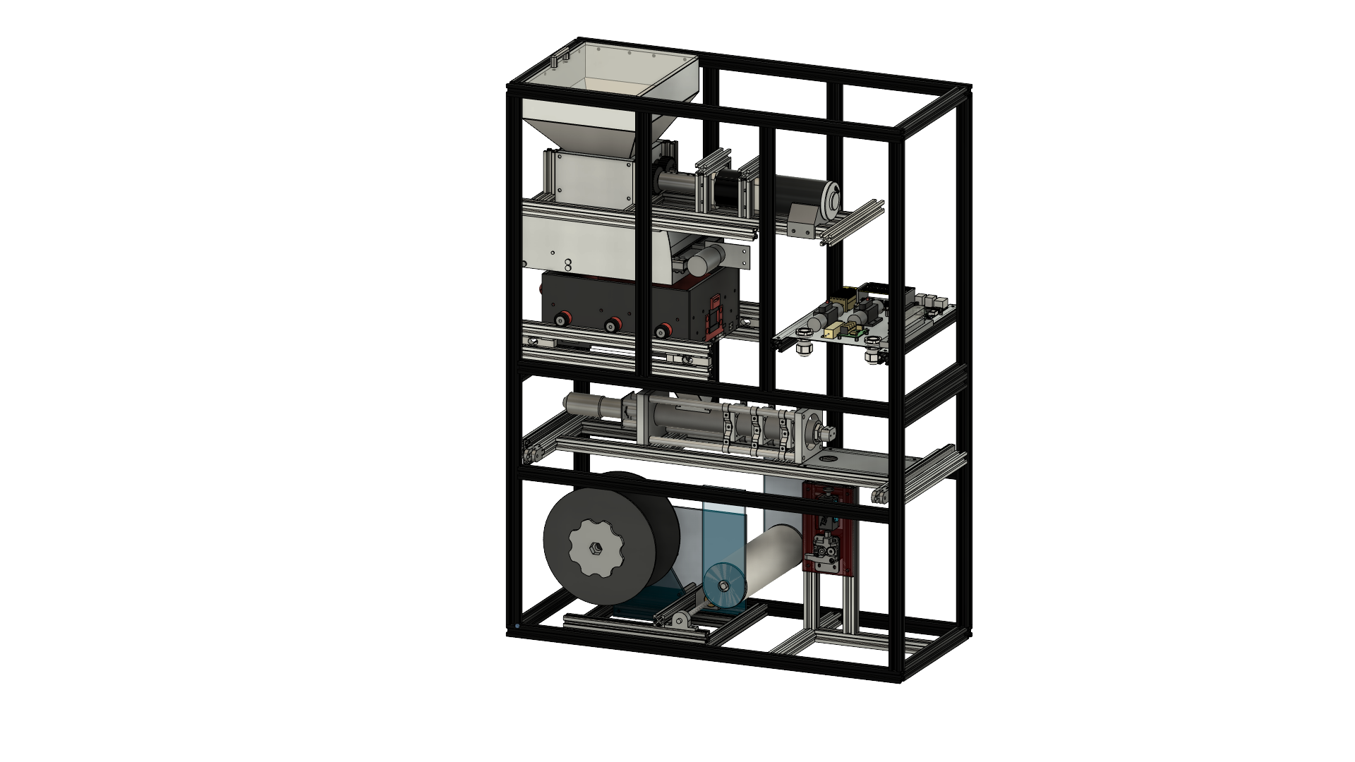
The L3HSDC requested a machine capable of recycling its large amount of scrap PLA plastic into reusable filament for their 3D printers. Our team was tasked with designing, building, and testing this recycling machine, which needed to break down the plastic into small pieces, melt those pieces into a molten state, extrude the melted plastic into filament, and wrap it onto a standard filament spool. In order to accomplish this, the project was divided into three main subsystems: Reducer, Producer, and Automation and Controls. The Reducer consists of all components integral to the breaking down, filtering, and storing of the plastic. The Producer consists of all components integral to melting, extruding, checking diameter, and spooling the plastic. Automation and Controls ties all components together by controlling electronics and mechanical assemblies, as well as constantly monitoring safety parameters.


Project Ojective
This recycling machine must take the customer’s discarded PLA plastic as input and output recycled PLA filament. To accomplish this, the plastic is shredded into very small pieces for uniform melting. The shredded plastic then enters a filtering mechanism before being held in a storage container. Upon process start, the small plastic pieces are fed into the extrusion mechanism, similar to injection molding technology, which melts down the solid plastic pieces into molten PLA. Once melted fully, the plastic is compressed and extruded as a continuous strand of recycled filament. This new filament is then measured to ensure the diameter is the same as the standard diameter for 3D printing filament. Finally, the recycled filament is wrapped onto a standard 3D printing spool via the spooling mechanism. The recycling machine is designed to be composed primarily of commercially available parts to ensure that the customer has little to no issues when finding replacements for worn or damaged components. Due to the dangerous nature of this machine and its various mechanisms, there are numerous safety barriers in place to ensure user safety while the machine is active. There are also safety parameters that continuously check data against nominal values in order to catch any system irregularities, such as overheating or motor malfunction. Additionally, the team is providing the customer with an operation manual, which includes safety guidelines, as well as a maintenance plan outlining the required service the product will need to ensure maximum safety, efficiency, and longevity when operating.

Manufacturing Design Methods
The largest challenge faced during the design and manufacturing of the recycler was attempting to create prototypes early in the design process. The goal of this was to address any design flaws that may have presented themselves, as well as to have more time if it was necessary to pursue a whole new design approach. Using heat analysis and static structural analysis in both Fusion 360 and ANSYS Workbench were essential when ensuring our designs were fully informed. Iterative design was the key to this project, as the CAD models for each of the core components of the machine were continually updated and improved upon until the final designs were solidified. However, this meant the design stage lasted longer than scheduled, which proved detrimental to our progress over time. Manufacturing for this project consisted primarily of using the water jet machine to cut out metal parts. Many parts for our Producer components were machined by hand or using the CNC mill. Any other parts that were custom designed were made using 3D printers. Prototypes in the early stage of the project also used 3D printed parts, as well as wood and acrylic parts cut on the large-format laser cutters.

Specification
Weight: ~150 lb. Size: 0.70m W x 0.94m H x 0.30m D (27.6" W x 37.0" H x 11.8" D) Storage capabilities: up to 2.5 kg of shredded PLA Process time (1 kg):

Analysis
Heat analysis and static structural analysis in both Fusion 360 and ANSYS Workbench were used when designing most parts due to the high temperatures inside a section of the machine. Calculations were done by hand as well as in Excel to determine torque and force in the shredder mechanism, as well as when determining rotation and translation speeds for the spooling mechanism.

Future Works
In the future, the final design for our machine could be improved upon as it is used in the L3Harris Student Design Center. Troubleshooting opportunities may arise that could require some redesigning of parts or slight modifications to system function.


Manufacturing Design Methods
The largest challenge faced during the design and manufacturing of the recycler was attempting to create prototypes early in the design process. The goal of this was to address any design flaws that may have presented themselves, as well as to have more time if it was necessary to pursue a whole new design approach. Using heat analysis and static structural analysis in both Fusion 360 and ANSYS Workbench were essential when ensuring our designs were fully informed. Iterative design was the key to this project, as the CAD models for each of the core components of the machine were continually updated and improved upon until the final designs were solidified. However, this meant the design stage lasted longer than scheduled, which proved detrimental to our progress over time. Manufacturing for this project consisted primarily of using the water jet machine to cut out metal parts. Many parts for our Producer components were machined by hand or using the CNC mill. Any other parts that were custom designed were made using 3D printers. Prototypes in the early stage of the project also used 3D printed parts, as well as wood and acrylic parts cut on the large-format laser cutters.


Society of Automotive Engineers Formula Car


Team Leader(s)
Mason Yaskovic, Sander Sorok

Team Memeber(s)
Shawn Nobles, Trishaa Mahesh, David Dacosta, Hamed Al Subhi, Michael Fleckenstein, Terna Chagu, Luis Maiz

Faculty Advisor
Dr. Darshan Pahinkar


Society of Automotive Engineers Formula Car   File Download
Project Summary
Project Description and Requirements The Formula SAE Senior Design project is a challenging undertaking that embraces the rigorous standards set by the FSAE competition board. The project's aim is to conceptualize, develop, fabricate, test, and optimize a racing car that adheres to the regulations stipulated by the FSAE governing body. The key milestones of the project involved designing and manufacturing the chassis, suspension, aerodynamic package, and driver interface systems. The 2022-2023 SAE team’s initiative is set to further develop the car that had been partially designed and built in the 2021-2022 year. Optimization, completeness, and taking the vehicle to competition are the core goals set forth by the team. Design Process and Key Features The initial challenge presented to the team involved gaining a deeper understanding of the work that had been completed on the car. From that point, identifying which components required redesign, further analysis, or need to be added entirely provided a clear direction from the team. The team was then segmented into five different subteams: Powertrain, Aerodynamics, Chassis, Suspension, and Brakes. An emphasis was placed on the Powertrain division this year in an attempt to optimize the previous year's vehicle. The final design showcases the following unique features: - A newly rebuilt Honda CB600rr four-cylinder racing engine, fitted with a student-built and designed intake and exhaust systems to meet FSAE compliance while maximizing power. - A custom-designed and built chassis with a torsional rigidity of 2065 Nm/deg. - A suspension designed in Optimum Kinematics fit uniquely for this vehicle. - A bespoke aerodynamic package designed with the intention of reducing weight whilst maintaining performance capabilities. - An entirely new wiring harness and sensor map fitted for the 2023 vehicle, along with refreshed ECU and dashboard display. - An adjustable pedal box fit to accommodate a 95th percentile driver.


Water Trash Collector


Team Leader(s)
Theo Cox

Team Memeber(s)
Theo Cox, Javier Demori, Ben Vilardebo, Patrick Stewart, Herman Castro, Alaina Michalczyk, Adnan Aljohani, Faisal Aldawsari

Faculty Advisor
Dr. Douglas Wilard Dept. Of Mechanical and Aerospace Engineering


Water Trash Collector   File Download
Project Summary
Our project's purpose is to design, fabricate, and test a semiautonomous watercraft that collects trash on the water's surface. We set goals for the collector's performance and usability. To achieve these goals, we divided the water trash collector (WTC) into five subsystems: Power, Electronical, Structural, Collection, and Navigation. When we began designing, we studied various marine structures, materials for durability and buoyancy, and preexisting products like what we designed.


Manufacturing Design Methods
The first challenge was ensuring the WTC is waterproof and hydrodynamic. As mechanical engineers, we usually focus on aerodynamics rather than hydrodynamics. We considered the typical water conditions of the Indian River Lagoon and compared it to marine structures best suited for the environment. We also researched the types of frames and compared the advantages and disadvantages for each from an economical and practical perspective. The structure we decided to mimic was a catamaran style frame to optimize space for collection and used common materials for easy construction and minimal cost. The second challenge our team faced was the electronics. In order to make the WTC autonomous, it had to have obstacle avoidance as well as GPS technology. None of the team members were proficient in coding, the language taught at Florida Tech is C++ and this project required Python; however, the electronics subsystem members reached out to peers and other resources to learn how to program their ultrasonic sensors. The major challenge navigation had was with the computer system, the Pixhawk. This flight controller is intended for drone use. We used the Pixhawk on the WTC so it could be controlled remotely and tracked in real time. The device had to be modified so it is compatible with the WTC rather than a drone.

Specification
The main specifications for this project were: 1. The collector shall be easily assembled by 3 able bodied people. 2. The collector shall fit within a standard pickup truck bed. 3. The collector shall be able to be assembled using only tools that are obtainable at a local hardware store. 4. The collector shall be able to hold 100 kgs of waste


Future Works
Future goals for this project involve making the whole assembly autonomous. Full autonomation includes being able to map a pre-determined course and the collector being able to follow that course while collecting waste.


Manufacturing Design Methods
The first challenge was ensuring the WTC is waterproof and hydrodynamic. As mechanical engineers, we usually focus on aerodynamics rather than hydrodynamics. We considered the typical water conditions of the Indian River Lagoon and compared it to marine structures best suited for the environment. We also researched the types of frames and compared the advantages and disadvantages for each from an economical and practical perspective. The structure we decided to mimic was a catamaran style frame to optimize space for collection and used common materials for easy construction and minimal cost. The second challenge our team faced was the electronics. In order to make the WTC autonomous, it had to have obstacle avoidance as well as GPS technology. None of the team members were proficient in coding, the language taught at Florida Tech is C++ and this project required Python; however, the electronics subsystem members reached out to peers and other resources to learn how to program their ultrasonic sensors. The major challenge navigation had was with the computer system, the Pixhawk. This flight controller is intended for drone use. We used the Pixhawk on the WTC so it could be controlled remotely and tracked in real time. The device had to be modified so it is compatible with the WTC rather than a drone.