
/prod01/fit-cdn-pxl/media/header-images/showcase-header.jpg)
Mechanical and Civil Engineering
Mechanical Engineering
3D Filament Recycler
Team Leader(s)
Connor EasleyTeam Member(s)
Connor Easley, Stephan Jean-Baptiste, Armando Loynaz, Brody Paulk, Meagan Prouty, Tai Roberts, Jack Salcedo, Vanessa Tohorton, Alex Tremblay, Ruhaan ZaveriFaculty Advisor
Dr. Anand B. NellippallilSecondary Faculty Advisor
Dr. Sayed E. Saghaian and Dr. Chiradeep Sen3D Filament Recycler File Download
Project Summary
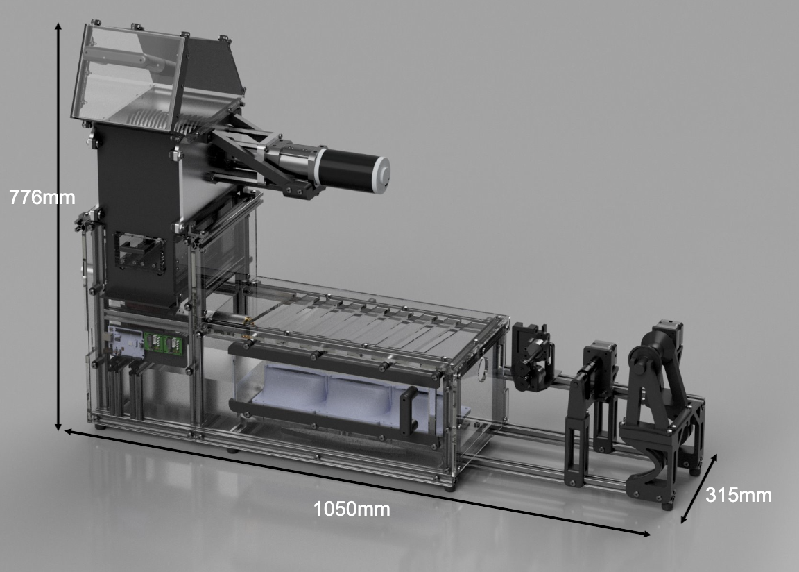
The 3D Filament Recycler project focuses on sustainability, aiming to reduce waste generated by the 3D print farm at our customer location, the L3 Harris Student Design Center (L3HSDC). This device will convert failed PLA prints and scrap into usable spools of filament, reducing plastic waste and lowering the material costs of purchasing PLA for the print farm. This machine begins the recycling process by breaking down scrap filament using its reclaimer subsystem. The material is then collected in a storage basin before moving into the extruder subsystem. During the extrusion process, the processed filament scrap is heated to 180 °C. The extruded filament is then moved through the cooling subsystem to maintain the desired diameter. Finally, the extruded filament is tensioned and spooled by the tensioning and spooling subsystems. Ultimately, this process allows the collected waste filament to be reprocessed into a new usable spool.Project Objective
The purpose of this project is to design and manufacture an integrated system for the L3HSDC that can recycle 3D filament waste by shredding, heating, and extruding it.Manufacturing Design Methods
The system is designed with a modular approach, comprising 6 separate subsystems that each accomplish a specific task in the recycling of PLA filament. The reclaimer is made from two waterjets and milled aluminum plates with bolted flange bearings. The 25 blades/blade guides, made of steel, and 25 spacers/spacer guides, made of aluminum, are cut using the waterjet. The reclaimer assembly is simple due to its tight tolerances, yet it still allows the blades to travel after being driven by the shaft. The blades and shaft are turned by a large motor via a 192:1 gearbox. The high-torque motor assembly is held to the reclaimer side plate by four 10-32-thread steel standoffs and an additional PETG-printed support carriage. The steel hexagonal shaft that holds the blades and spacers was lathed to 15 mm diameter to fit the side flange bearings, with an outer diameter tolerance of ±0.5 mm. The entire reclaimer is then held together with stainless-steel threaded rods, paired with a large PLA front block that serves as an inlet. The extruder was purchased commercially and sits on a slide-in modular support frame made from waterjet-cut and milled aluminum. The storage box and filter shelf are made of laser-cut acrylic panels and PETG/PLA-printed railings, with a total capacity of 2kg. The cooling fans are commercial PC fans mounted on a PETG/PLA-printed support frame. The tensioner subsystem is made of a PETG/PLA-printed housing for both stepper motors and uses a linear screw attached to a NEMA 17 stepper motor, allowing it to traverse vertically. The tensioner wheels are printed from PETG/PLA and have a rubber grip along the outside to grip passing filament. The spooler is entirely made of PETG/PLA for the frame, shifter, and screw mechanism, with each being driven by two additional stepper motors. The entire system sits inside a 20mm x 20mm aluminum t-slot frame, allowing for modularity and easy switching of subsystems. The brackets that hold the frame together are made from both PETG and waterjet-cut/milled aluminum. The frame is then fully enclosed with laser-cut acrylic panels that allow bolts to pass through to be easily fastened to the frame. Each subsystem is controlled and powered via the electronics board, which sits on its own removable acrylic panel under the cooling fans. This allows air to be sucked from under the frame, away from the electronics and into the hot filament.Specification
Dimensions: 1040 mm x 260 mm x 740 mm Reclaimer Inlet: 230 mm x 150 mm Blade: 114 mm Spacer: 90 mm Storage Box: 23 mm x 9 mm x 6 mm Electronics: Arduino MEGA,1000W 12V Industrial Power Supply, 12V 192:1 DC Motor, 12V DC Extruder Motor, 3 40W Heating Cartridges, 3 28BYJ Stepper motors with ULN2003 drivers, 3 12V DC cooling fans, 4 N-mosfet 5A modules, 12V-5V buck converter, and 2 NEMA 17 Stepper motors with A988N motor driver.Analysis
All structural components of this project were analyzed in ANSYS Workbench. Specifically, the static structural tool was used to analyze the machine's structural stability and identify potential deformation locations. The static structural tool was also used to analyze the reclaimer’s blades to see where deformation and deflection will occur during the filament breakdown process. The fluent and transient heat tools were used within the ANSYS Workbench to determine the rate of heat transfer throughout the extruder system. These tools were also used to analyze heat distribution throughout the extruder system. Altogether, these simulations provided strong evidence that the 3D Filament Recycler would function as intended under ideal conditions.Future Works
Future work for this project includes expanding its operating capabilities to include processing PET-G. Currently, the L3HSDC print farm uses both PLA and PETG filaments to create student projects, producing waste from both. While the 3D Filament Recycler project focused on PLA and its material properties, the machine has the potential to process PETG because the extruder can extrude both filaments. This machine could easily expand its operating capability by creating a code in the user interface that allows PETG to be processed within the material properties specified for it.Acknowledgement
We would like to thank especially our GSA Sebastian Donall, Royce Jacobs, Lewis Moth, and Zac Schardt, along with the L3 Harris Student Design Center and Machine shop staff, who have contributed meaningfully to our experience.LMCO/Navy Air Pallet for Materials Handling
Team Leader(s)
Samantha Ryan, Ryan ZernekeTeam Member(s)
Joshua Bible, Justin Conner, Brycen Haner, Nevan Juteram, Alexander Lacy, Gavin Lanka, Henry Lewis, Samantha Ryan, Ryan ZernekeFaculty Advisor
Dr. Anand NellippallilSecondary Faculty Advisor
Junot DamenLMCO/Navy Air Pallet for Materials Handling File Download
Project Summary
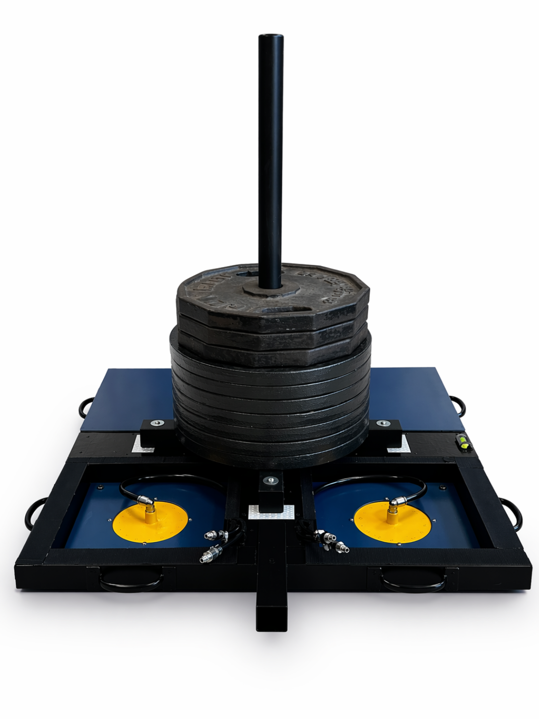
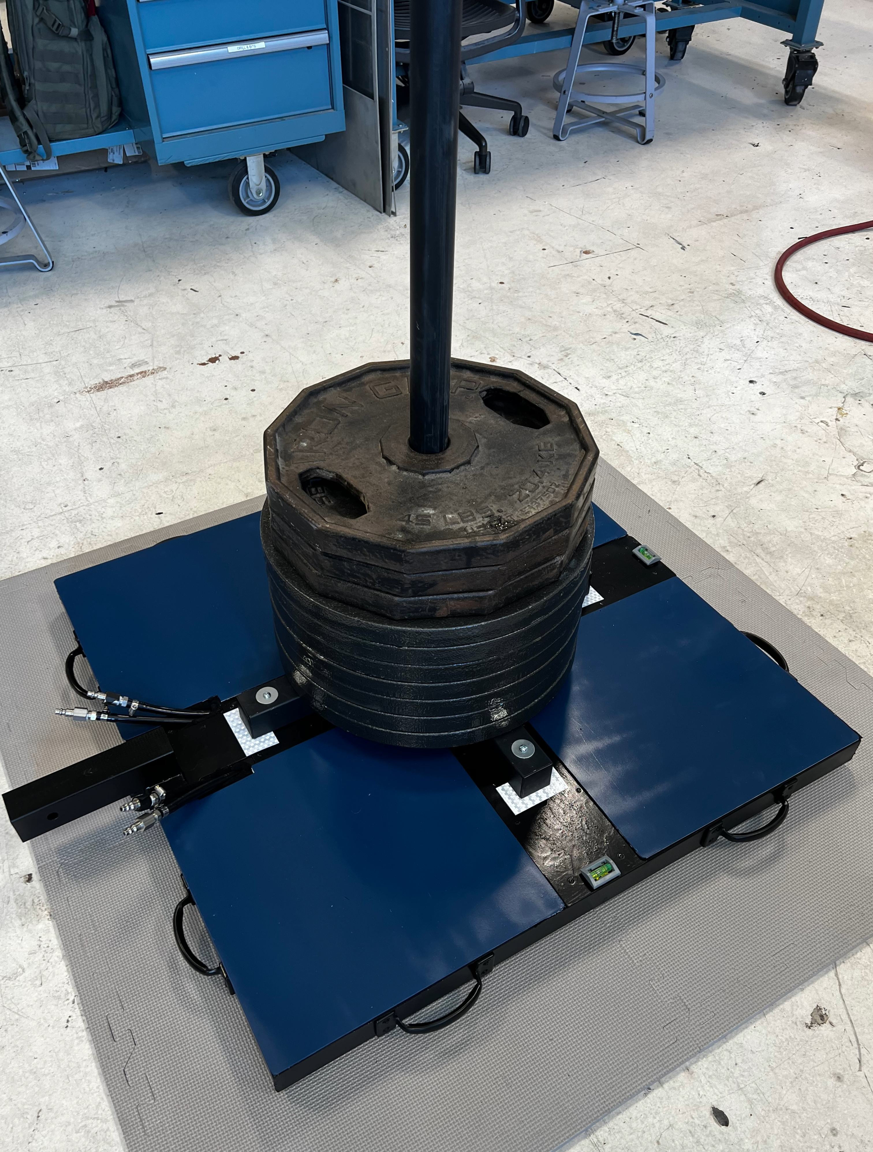
An Air Bearing System is a load-bearing material transport system used by customers Lockheed Martin Corporation (LMCO) and the United States Navy. These systems help move large equipment and sensitive items around their facilities. The Air Bearing System is a non-contact, frictionless bearing system that uses a thin layer of pressurized air forced through small holes or porous material to create an air cushion between the ground and the moving device. The Air Pallet is a subsystem of the Air Bearing System and is responsible for lifting the load. Technical challenges of this problem include ensuring no magnetic or electronic components are present in the final design, ensuring the air casters generate no more than 0.5” of vertical lift, and maintaining a level system in operation. This is a reduced scale projected from customer use to student use. The air casters in this system design are scalable to meet a larger scale or smaller scale, if necessary, as they are a soft goods manufactured item. This student design aims to address the current system issues of structural rigidity and maintenance hazards by using a 'drop-in' air caster design to allow maintenance to be performed without accessing the underside of the Air Pallet. In this student design the drive tractor and air pallet are separate entities which differs from the current competition, Hovair and AeroGo. A combined budget of $10,000 was allocated for both projects and split evenly giving both teams $5,000. From this budget, the team has spent $4,001.48 on all materials and tooling necessary to manufacture the Air Pallet, leaving a balance of $998.52.Project Objective
There is a need to develop an Air Bearing System that will provide smooth, level, omnidirectional movement of a significant Load for facility operations. The current system has experienced issues with structural rigidity and requires complex maintenance operations using hazardous solvents, adhesives, and coatings. Additionally, it is aged and due for a design refresh focusing on efficient use of space, manpower, and time. The goal is to minimize these factors and improve environment and economic efficiency, while ensuring the safety and precision of the Load operations. The resulting product will benefit an internationally-collaborative global defense program.Manufacturing Design Methods
The frame of the Air Pallet is made of 304 stainless steel, 2-in X 2-in square tubing of 1/16-in thickness purchased from Grainger. The air casters are made of 304 stainless steel sheets of 3/16-in thickness purchased as a replacement from OnlineMetals. The load design is a generic steel weight tree.Specification
The Air Pallet is compliant with MIL-STD-1472H (design criteria fro human engineering) by featuring provisions for manual handling with the air supply shut off and in an unloaded state. All non-electronic controls are visible to the operator from the operator position, as well as the spotter from the spotter position.Analysis
FEA was performed on the loading surface of the Air Pallet to determine if the material chosen could withstand the loading requirement. Analysis was performed on both the full system model and a 1/4 system model to determine a Factor of Safety of 3.71.Acknowledgement
The Air Pallet team would like to extend gratitude to our customer advisors Lauren Bowers and Anderson Crookshanks from Lockheed Martin and to Armstron Ekpete of the U.S. Navy.LMCO/Navy Drive Tractor
Team Leader(s)
Nicholas Czincila, Andrew PestoneTeam Member(s)
Nicholas Czincila, Andrew Pestone, Santiago Florez-Tascon, McKenzie Winder, Kalvin Long, Ashlyn Redding, Diana Viherik, Joseph Phan, Noah Rodriguez, Nick Norman, Brandon RibeiroFaculty Advisor
Dr. NellippallilSecondary Faculty Advisor
Junot DamenProject Summary
Most industrial complexes contain heavy items and machinery that often need to be moved quickly and precisely. Limiting the amount of time that is spent on moving items while keeping all operators safe and efficient is critical for this project. Currently, all competition comes from existing solutions such as those presented by Hovair and AeroGo. This new design aims to separate the pallet and handles, creating a drive tractor and pallet system. The finalized design for this project is made up mostly of an aluminum 6061 tubular frame supported by Omni-Ball wheels. These wheels allow for 360-degree rotation of two hemispheres around a central axis, creating smooth, omni-directional movement for the tractor. The device will facilitate air flow from an external source, feeding said airflow to the air pallet (which is carrying the load). All pneumatics for the system will have multiple fail safes throughout the design. Multiple points where the air can be dumped and stop system motion are included as well as pressure regulators at the operator’s position. To connect the device to the air pallet, a locking mechanism is employed to create a rigid connection between the tractor and pallet. The device also splits the airlines into 4 outlets that plug into the air pallet, creating another connection. This project could be scaled to facilitate another pallet. The device has been ensured to withstand the force of two pallets, though only one is required for demonstration purposes. The team has ordered $4291.30 in materials with $708.70 unspent following the completion of the project. The total budget for this project was $10,000 split between the air pallet and drive tractor teams equally and was not exceeded by either team.Project Objective
There is a need to develop an Air Bearing System that will provide smooth, level, omnidirectional movement of a significant Load for facility operations. The current system has experienced issues with structural rigidity and requires complex maintenance operations using hazardous solvents, adhesives, and coatings. Additionally, it is aged and due for a design refresh focusing on efficient use of space, manpower, and time. The goal is to minimize these factors and improve environment and economic efficiency, while ensuring the safety and precision of the Load operations. The resulting product will benefit an internationally-collaborative global defense program.Manufacturing Design Methods
The majority of the device has been created with 1.5in / 2in Aluminum 6061 tubing. This was extruded aluminum ordered from McMaster Carr. These were then cut and welded within the on-site machine shop. The other major manufacturing component was additive manufacturing in the form of 3D printing. Many clips and most of the Omni-Ball wheels were created with 3D printing methods.Specification
The Drive Tractor has a few key specifications that make the device special. At the operators position, there is a plate that houses an emergency dump valve as well as a filter and gauge combination. Below this, attached to the frame, is the 4-station manifold. This manifold allows for the individual regulation of air flowing the the separate castors within the air pallet. It intakes air from a single source and splits it into 4 separate lines. Finally, at the bottom of the device is the locking mechanism. This consists of a plate that sits on two T-slotted framing pieces, negating the need for suspension. This allows the lock to slide up and down with the Pallet as it inflates. On the plate is a store bought 2in x 2in trailer hitch, that allows for positive engagement between the Tractor and Pallet.Analysis
All analysis for this device was performed in ANSYS. Structural stress tests were performed to ensure project stability. It was important to conduct these tests so that the lightest, yet strongest material could be chosen while staying within the required design parameters (such as factor of safety). This also helped to point out critical stress points that were addressed during the manufacturing phase.Future Works
For the future, more focus can be given to the translation. We were unable to finish the Omni-balls in time for showcase (a separate back-up translation device was available). Focusing on this would be imperative for the novelty of the project in the future. Other things to consider are the stability of the connection at the hitch as there is a small amount of play which produces slop in the operation.Acknowledgement
The Drive Tractor team gratefully acknowledges customer support from Lockheed Martin representatives Lauren Bowers and Anderson Crookshanks, and Armstrong Ekpete of the U.S. Navy.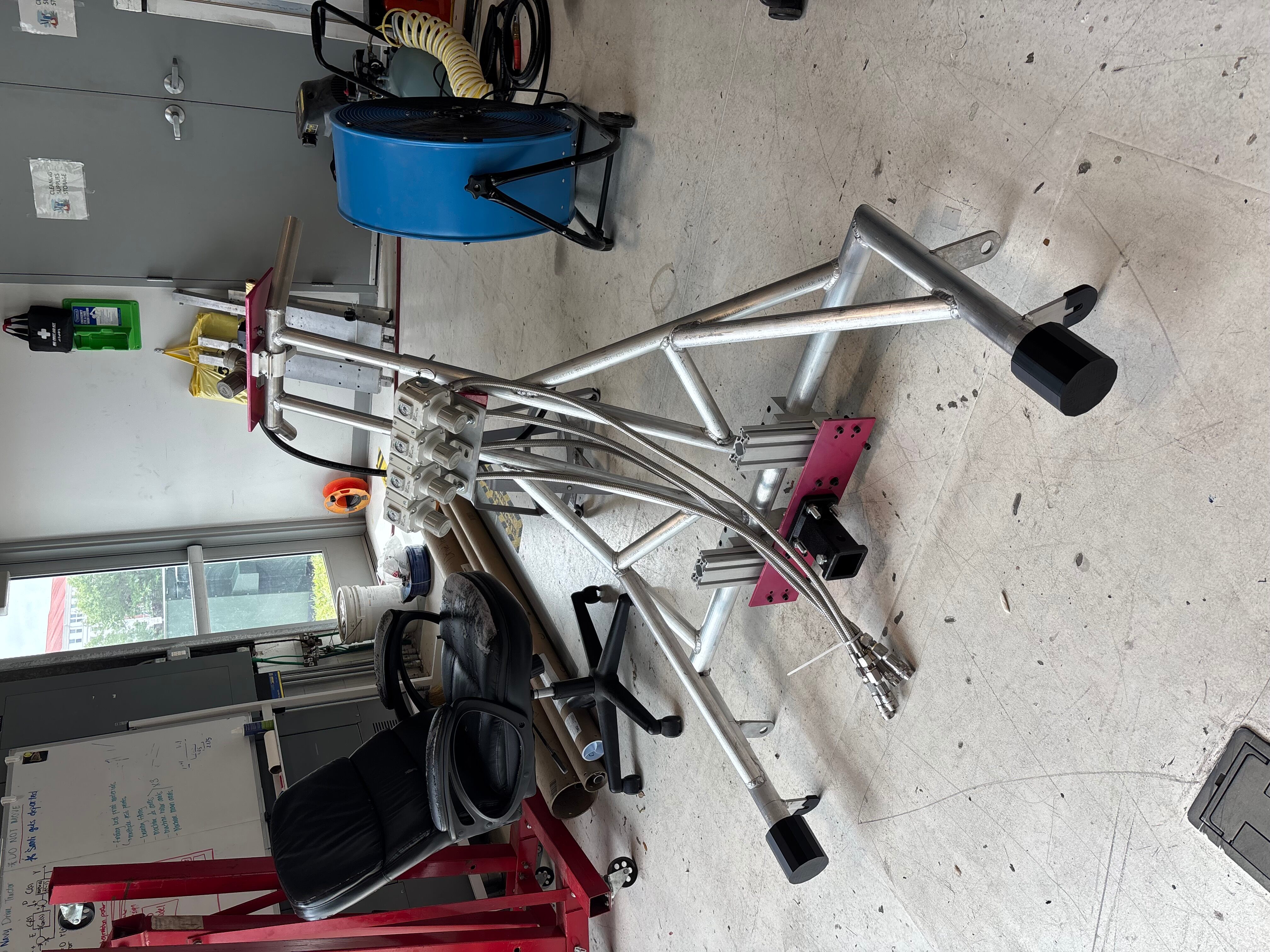
MATEAR System
Team Leader(s)
Kylie Stong (PM), Adel Siraeva (SE)Team Member(s)
Kylie Stong, Amiana Mata, Julianna Bartus, Adel Siraeva, Jack Minners, Rayna Doty, Cameron (Noelle) Deen, Lilly Davies, Matthew SkwiotFaculty Advisor
Kim-Doang NguyenSecondary Faculty Advisor
Anand Balu NellippallilMATEAR System File Download
Project Summary
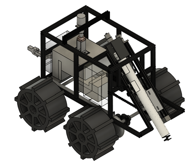
Our project involves designing an attachment for the Clearpath Robotics Husky A200 rover. The primary objective of this system is to collect lunar regolith from the surface of the Moon and process it into usable building materials. The overall goal is to provide a cost-effective method for constructing infrastructure on the Moon using in-situ resources. The attachment utilizes an auger mechanism to collect regolith, which is then directed through a funnel into a mold located on the base of a furnace. This base is mounted on rails, allowing it to move and enclose the mold in the furnace where the material is heated to approximately 1000°C to form a solid brick. After the heating process, the mold cools before the base of the furnace detaches and travels back along the rails, depositing the finished brick onto the lunar surface.Project Objective
The objective or goal of the project is to create a cost-effective way to build infrastructure on extraterrestrial bodies.Manufacturing Design Methods
The design process began with the development of functional models and system architecture diagrams to define energy flow, material movement, and subsystem interactions. Based on this, the system consists of six primary subsystems: collection, compression, thermal, internal transportation, mobility, and controls. Each subsystem was designed using CAD software to create detailed assemblies and manufacturing drawings, allowing for accurate visualization and fabrication planning. The collection subsystem uses an auger enclosed within a tube to efficiently excavate and transport regolith. The auger is motor-driven and supported by a lead screw system that controls vertical motion, ensuring precise interaction with the lunar surface while directing material into a funnel. The compression subsystem uses a motor and threaded rod connected to a Kast-O-Lite piston head to apply controlled force, and retracts after compression to maintain furnace insulation. The thermal subsystem consists of an electrically powered furnace capable of reaching 1000°C, with layered insulation including ceramic fiber and Kast-O-Lite within an aluminum shell. Heating coils generate thermal energy, while a thermocouple provides temperature feedback. The internal transportation subsystem uses a chain-driven rail system to move the mold through compression, heating, cooling, and deposition stages with consistent positioning. The mobility subsystem includes a lightweight aluminum frame, 3D-printed airless wheels with added traction, and a U-bolt hitch connection to the Husky A200 rover. The controls subsystem coordinates all operations using a Raspberry Pi 5, enabling both autonomous processes and user control through a web-based interface, while sensors provide real-time system feedback. Manufacturing methods were selected based on cost, material properties, and available resources. Aluminum extrusion was used for the frame, additive manufacturing for custom components, and refractory materials for high-temperature elements. Standard off-the-shelf components were incorporated to simplify assembly and reduce cost.Specification
Dimensions: 87 in x 28 in x 40 in Attachment: 48 in x 28 in x 40 in Rover: 39 in x 26.5 in x 15.5 in Auger: 22 in x 7 in x 18 in Rails: 24 in x 13 in x 6 in Furnace: 12 in x 10 in x 9 in Wheels: 12 in x 6 in x 11 in Electronic boxes: 6.5 in x 3.5 in x 10.5 in Electronics: Raspberry Pi 5 4GB, 12V 5200mAh Li-ion Battery, 12VDC 10RPM Worm Geared Motor 8mm D-shaft (rails), 12VDC 10RPM Spur 300:1 Gear Motor (compressor), 2 12VDC 66RPM High Torque Micro Gear Motor (auger), 2 L298N Motor drivers, OV5647 Rasp pi camera, BOJACK DS18B20 Temperature Sensor Module, Inkbird High Voltage PID Temperature Controller, SSR-40 DAAnalysis
For this project all structural and thermal analysis was completed in ANSYS Workbench. The transient thermal tool was used to simulate the heating and cooling process the furnace will undergo to make the bricks. This tool was also used to optimize the insulation and ensure the heat generated will not affect the system as a whole. To simulate the system under external and internal loads the static and transient structural tools. The structural tools were used to locate possible failure points due to stress and deformation. This allowed the team to optimize the system to improve the overall design. These tools allowed the team to optimize the system and operate the system at ideal conditions. Future Works: Focus on improving system efficiency, durability, and readiness for space operation. One major area of improvement is the furnace, where further testing can be conducted to optimize heating time, insulation performance, and energy consumption. Also refining the collection and transportation systems to reduce clogging and improve material flow, particularly in low-gravity environments.Acknowledgement
The MATEAR Team thanks our graduate student assistant Sebastian Donall, our customer Candela Solis Zampini, and the Florida Tech L3HSDC staff.Psi Epsilon Station
Team Leader(s)
Ember Clark, Alex FrenchTeam Member(s)
Ember Clark, Zac Hardin, Jasper Stevens, Cole Capawana, Carter TomaskyFaculty Advisor
Darshan PahinkarProject Summary
We are building a fully operational Rankine Cycle to demonstrate to students taking thermodynamics how the cycle looks and works from a physical perspective. For this we have made a boiler, turbine, condenser, and pump by hand.Project Objective
Help teach students how the Rankine Cycle works from a physical perspective.Manufacturing Design Methods
To design the boiler, there was a lengthy research period followed by a series of long meetings discussing designs. Most things were designed in onshape before being made. For manufacturing, we had to learn to cut and thread pipe, cut steel rods and plates, laser cut wood, 3D print high temperature filaments, and we had to make our own sprockets.Future Works
Since this is a personal project, there's already plans to pass this down to more people to work on. The next things that will be worked on is a proper battery storage, sensors that send data to a GUI, and an entire boiler overhaul including all new piping and forced air.Acknowledgement
We would like to thank Dr. Najafi and Alex Larivee for their help with calculations. We'd also like to thank Cypress Decker for their help with the turbine design. And lastly we'd like to give a big thanks to Micheal Hoadley for his generous donation and wisdom. Without him, the project would've never happened.Solar Panel Augmentation via Regulated Cooling and Cleaning (SPARCC)
Team Leader(s)
Zachary Rodgers (PM), Connor Fromme (SE)Team Member(s)
Zachary Rodgers, Connor Fromme, Mohammed Al Jahwari, Jack Connor, Nicolas Hubley, Adrian Kingdollar, Iain LeRoy, Maria Jesu Munoz, Ashton StringerFaculty Advisor
Dr. Hamidreza NajafiSecondary Faculty Advisor
Dr. Anand NellippallilSolar Panel Augmentation via Regulated Cooling and Cleaning (SPARCC) File Download
Project Summary
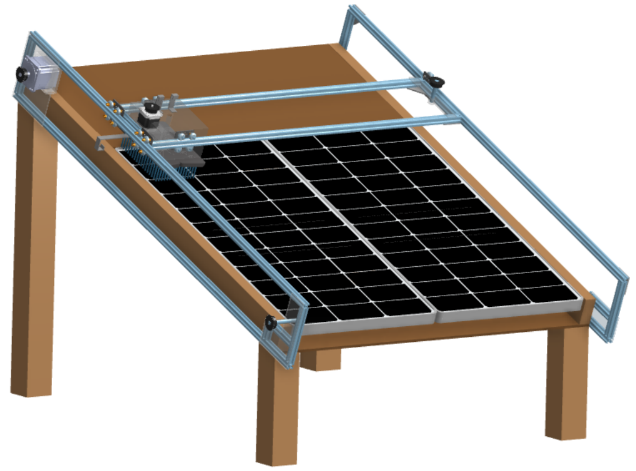
The Solar Panel Augmentation via Regulated Cooling and Cleaning (SPARCC) project focuses on improving the performance, efficiency, and reliability of photovoltaic (PV) solar panels by developing an integrated cooling and cleaning system. Rather than addressing a single source of efficiency loss, the SPARCC design combines thermal management and surface maintenance into a single cohesive system, allowing panels to operate closer to their optimal conditions over extended periods. This approach targets the two primary factors that reduce solar panel output in real-world environments: elevated operating temperatures and dust and debris accumulation on the panel surface. The system incorporates a passive cooling subsystem that utilizes heat sinks, phase change materials, and a solar chimney to enhance heat transfer away from the panel. Heat sinks increase the available surface area for conduction and convection, while phase change materials absorb excess thermal energy during peak conditions and release it gradually as temperatures decrease. The solar chimney promotes natural airflow across the back of the panel, creating a continuous convective cycle that further reduces operating temperature without requiring additional energy input. Together, these methods provide a cost-effective and energy-efficient solution for thermal regulation. In addition to cooling, the SPARCC system includes an active cleaning subsystem designed to maintain surface clarity and maximize light absorption. This subsystem consists of a mechanically driven brush that traverses the panel via a chain-and-rail system, combined with a controlled spray mechanism that assists in removing stubborn debris, such as dust, salt, and organic buildup. The coordinated motion of the system provides complete, uniform coverage of the panel surface along a structured two-dimensional cleaning path. This ensures consistent performance while minimizing the risk of surface damage and reducing the need for manual maintenance. The overall system is supported by a modular mechanical framework that enables adaptability across different solar panel configurations. The design incorporates aluminum extrusion rails, a chain-driven motion system, and a microcontroller-based control architecture to manage movement along both horizontal and vertical axes. This allows the system to operate in a repeatable, controlled manner while maintaining alignment and reliability over extended use. Emphasis was placed on using commercially available components and straightforward manufacturing methods to reduce cost and simplify assembly. Throughout the design process, a combination of modeling, simulation, and experimental testing was used to validate system performance and guide design decisions. Finite element analysis (FEA) was conducted to evaluate temperature distribution across the panel and determine the optimal placement of heat sinks, ensuring that cooling elements were positioned in areas of highest thermal concentration. Additional testing and analysis were performed to assess cleaning effectiveness, structural integrity, and overall system efficiency. Performance metrics, including power output, temperature reduction, and operational consistency, were used to compare the augmented system to a standard solar panel configuration. The final SPARCC design demonstrates the feasibility of a combined cooling and cleaning approach for improving solar panel performance. By maintaining lower operating temperatures and cleaner panel surfaces, the system can increase energy output, reduce efficiency losses, and extend the operational lifespan of PV systems. Furthermore, the emphasis on modularity, durability, and cost-effectiveness supports the design's scalability for larger installations, making it a practical solution for both small and utility-scale solar applications.Manufacturing Design Methods
The SPARCC system was designed using a structured engineering approach that emphasized modularity, manufacturability, and ease of assembly. The design process began with subsystem identification, where the cooling, cleaning, structural, and control components were developed independently and later integrated into a unified system. Iterative design methods, including concept generation, decision matrices, and CAD modeling, were used to refine each subsystem and ensure compatibility within the overall architecture. Manufacturing methods were selected based on cost, material availability, and ease of fabrication. The structural frame and solar chimney were constructed using commercially available lumber and assembled with standard fastening methods, including screws and wood adhesive. Aluminum extrusions were used for the rail system due to their strength-to-weight ratio and ease of assembly, enabling precise alignment and smooth mechanical motion. Off-the-shelf components, such as motors, sprockets, and wheels, were incorporated to reduce manufacturing complexity and improve system reliability. Custom components, including mounting brackets and support structures, were designed in CAD and manufactured using conventional machining and fabrication techniques where necessary. The heat sinks were attached to the rear surface of the solar panel using thermally conductive adhesive to maximize heat transfer efficiency, while holes were introduced in select designs to enhance airflow and convective cooling. The cleaning subsystem was designed with a chain-driven mechanism to provide controlled motion across the panel surface while maintaining consistent contact pressure. The integration of mechanical and electrical components was carefully considered during the design phase to ensure proper routing, protection, and maintenance accessibility. Overall, the manufacturing and design approach prioritized a balance between performance, cost-effectiveness, and scalability, enabling the SPARCC system to be realistically implemented and adapted for a variety of solar panel configurations.Specification
The SPARCC system is designed to meet a set of performance, structural, environmental, and operational specifications derived from system requirements. The primary performance specification is that the system must produce a net positive increase in energy efficiency compared to a standard solar panel configuration. This is achieved by reducing thermal losses and maintaining surface cleanliness to support optimal power generation. The system must also contribute to increased revenue generation by improving overall energy output. From a cleaning and thermal standpoint, the system must effectively remove particulates and debris such that the panel operates at approximately 90% efficiency, while also regulating temperature to maintain operation within a nominal range. The cleaning process must be consistent and controlled, with the ability to adjust cleaning frequency as needed. Structurally, the system must be durable and withstand environmental conditions, including exposure to water, dust, ultraviolet radiation, and high wind speeds. The design must be corrosion-resistant, maintain mechanical integrity, and achieve a sufficient safety factor to prevent failure under loading conditions. Additionally, the system must not cause damage to the solar panel during operation. Environmental and regulatory specifications require that the system does not negatively impact surrounding conditions, including preventing contamination of groundwater and avoiding air pollution. The system must also maintain safe operation under repeated use and exposure to outdoor conditions. Finally, the SPARCC system must be modular and adaptable, allowing it to be applied to various solar panel configurations. Components should be replaceable to support maintenance and longevity, and the overall design must remain cost-effective, easy to install, and suitable for real-world implementation.Analysis
: The performance of the SPARCC system is evaluated through a combination of theoretical analysis, modeling, simulation, and experimental testing to quantify its impact on solar panel efficiency. Thermal analysis focuses on the effectiveness of passive cooling methods, including heat sinks, phase change materials, and natural convection through the solar chimney, in reducing panel operating temperature. Lower panel temperatures are expected to directly improve electrical efficiency and reduce long-term material degradation. To support this, finite element analysis (FEA) was conducted to evaluate heat transfer behavior across the solar panel and determine the optimal placement of heat sinks. The simulation modeled temperature distribution under operating conditions and compared different heat sink configurations based on their ability to reduce peak temperatures and improve overall heat dissipation, and the results from the FEA guided the final arrangement of heat sinks by identifying regions of highest thermal concentration and positioning cooling elements to maximize conductive and convective heat transfer. Mechanical analysis is conducted to ensure the structural integrity and reliability of the system under operating conditions, including evaluating load distribution, motion consistency, and the durability of moving components such as chains, motors, and support structures. The cleaning subsystem is analyzed for its ability to effectively remove debris while maintaining appropriate contact pressure to avoid surface damage. Energy and performance analysis compares the output of a solar panel equipped with the SPARCC system to that of an unmodified panel under similar environmental conditions, using metrics such as power output, efficiency, and temporal consistency to assess system effectiveness. Additional analysis considers cost-benefit implications, including potential increases in energy generation and overall return on investment, and the combined results provide a comprehensive evaluation of system performance and validate the design approach.Future Works
Future development of the SPARCC system will focus on improving performance, scalability, and real-world applicability. One area for improvement is optimizing subsystem integration, particularly refining the placement and effectiveness of phase change materials and heat sinks to maximize thermal regulation. Additional testing can be conducted to determine the most efficient cleaning frequency and to further reduce water or energy consumption during operation. Automation and control systems offer another opportunity for improvement, as future iterations could incorporate sensors to monitor temperature, debris levels, and environmental conditions, enabling the system to operate adaptively rather than on a fixed schedule, thereby improving efficiency and reducing unnecessary operations. From a manufacturing perspective, future work may explore alternative materials and fabrication methods to reduce cost and improve durability, and scaling the design for large solar farms will also require consideration of system deployment, maintenance logistics, and integration with existing infrastructure. Long-term testing in outdoor environments will be necessary to evaluate durability, reliability, and overall system lifespan, and these improvements will help transition the SPARCC system from a prototype to a commercially viable solution.Acknowledgement
The SPARCC team would like to thank Dr. Hamidreza Najafi, Dr. Anand Nellippallil, Mr. Sebastian Donall, the L3HSDC staff, and the machine shop staff for their guidance, support, and contributions throughout this project.Variable Arm Reach Extender (VARE)
Team Leader(s)
Matthew Gorton (PM), Adam Johnson (SE)Team Member(s)
Matthew Gorton, Adam Johnson, Kaleem Bocus, Quin Fredrickson, Vaughn Havins, James Koethe, Leira Maynard, David Mierzejewski, James Moore, Joonhyung SiFaculty Advisor
Dr. Anand B. NellippallilSecondary Faculty Advisor
Dr. Seong Hyeon HongProject Summary
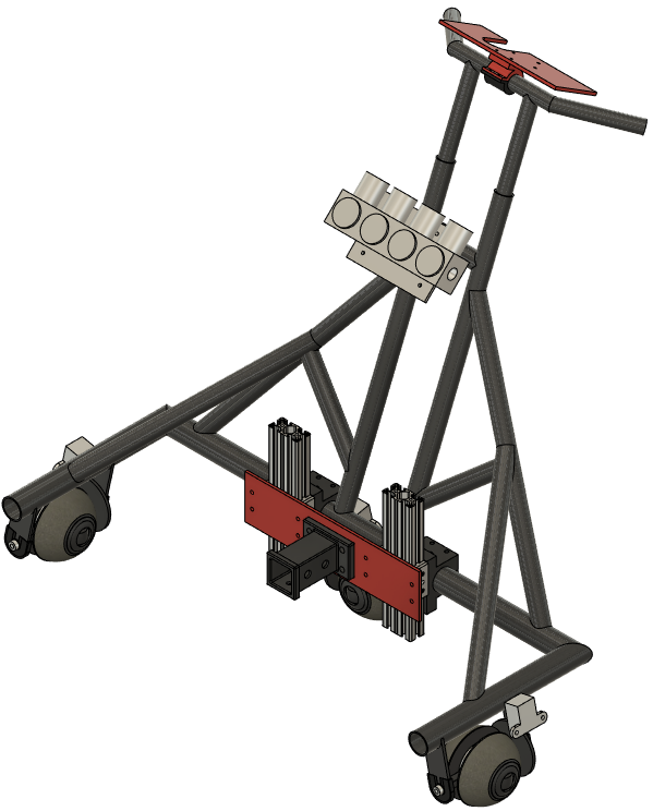
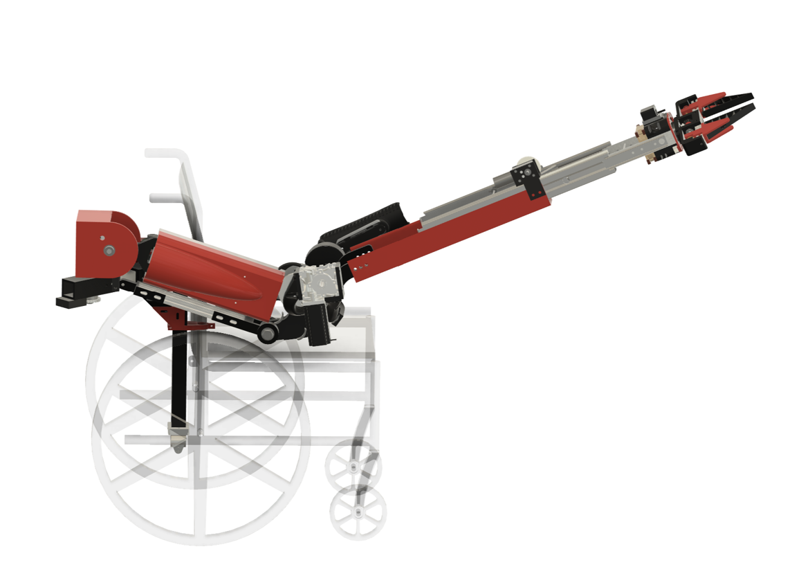
The purpose of the Variable Arm Reach Extender is to improve upon the standard reach extender, better assisting those with physical disabilities by meeting the end user's needs. This device functions by using a flexible end effector to grasp and form around objects of different shapes and sizes, while also being able to rotate and extend out by 14in from the user to grab objects from afar. A gravity-compensation system generates mechanical torque at the device's elbow joint to counteract any forces or torques the user experiences as they maneuver the device. All of this mounts directly to a support structure designed to bear all of the device's weight and reduce strain on the user, while also being able to lock in any position the user would like. All of these subsystems integrate to produce a device capable of lifting and maneuvering objects without placing any stress on the user.Project Objective
Design a reach extender that improves on the benchmark, leveraging engineering principles to design for improved reach, proper load distribution, and precise gravity compensation.Manufacturing Design Methods
The VARE system is split into five individual subsystems designed to fully integrate together for a seamless, cohesive experience. The first system is the End Effector system, designed to improve upon the benchmark by incorporating 3D-printed fin-ray grippers made of TPU. The dynamic wrist is seated inside a 3D printed PETG housing with off-the-shelf gears and an electric motor powering the wrist, as well as another motor powering the jaws on a power screw. The second system is the Reach Extension system. This was done using a set of off-the-shelf drawer slides and a pulley array run by 3D printed PLA followers on aluminum rods mounted directly to the rails. A motor driving a rack and pinion allows it to be driven back and forth via the human interface. The third subsystem is the gravity compensation system. This system uses a series of off-the-shelf and machined pulleys, water jet gears, as well as injection molded gears, and off-the-shelf springs to create a mechanical torque generator capable of canceling any torques or forces past the elbow joint between gravity compensation and reach extension. Other manufacturing methods, such as manual lathe and welding, were also used to create the brackets for the spring system, as well as the follower rods for the spring system. Off-the-shelf parts included are electric motors, power screws, bearings, and shaft couplers, etc. The fourth subsystem is the Structural subsystem. This system consists of two welded housings made out of 0.25in thick 6061-T6 aluminum plate. Machining was used to make the inner housings linking both joints together, as well as the main link between joints. 1566 carbon steel shafts were used to allow all joints to rotate smoothly on bearings. The locking pawl systems used 0.25in thick 6061-T6 aluminum plating that was water-jetted to get the pieces. Two servo motors were used to lock and unlock the pawls via a cable. The final subsystem is the control system, which links all systems together. This system consists of custom 3D printed motor mounts, battery mounts, and covers made of PLA. Other components include Arduinos, motor drivers, and encodersSpecification
Designed to meet ISO-21856 requirements and test methods. -End Effector: Max object weight 2kg, max object width 8.9cm, NEMA 17 Stepper Motor -Reach Extension: UXCELL worm gear motor, Max extension 14in, Max extension rate 8in/s -Gravity Compensation: 36V BLDC motor, NEMA 23 worm gear motor, 70NM of counter torque. -Structure: 2x Servo motor, minimum FOS of 4, max distance from chair: 12in -Controls: DM542TE Digital Stepper Driver, BLD-510B brushless motor driver, A4988 stepper driver module, L298N stepper driver board, DROK CNC DC buck converter, KBT 36V 8AH Li-ion batteryAnalysis
All FEA was performed using ANSYS static structural analysis. ANSYS was used to determine areas of high stress concentration for the structural subsystem and to optimize for a minimum factor of safety of 4 with a max deformation of under 1cm at full extension. ANSYS was also used to determine the factor of safety and deformation of the reach extension system for structural safety and rigidity.Future Works
Ideally, future work on this project would include optimizing the device for size and weight, and utilizing composite materials to reduce the need for a high factor of safety per ISO 21856. The future of this project would also include expanding the device's weight capacity to allow it to pick up heavier objects and allow for two degrees of gravity compensation.Other Information
References: [1] ASPE. (2013, Jan 6). Updated Analyses of Trends in Use of Assistive Devices. Retrieved from ASPE: https://aspe.hhs.gov/reports/updated-analyses-trends-use-assistive-devices-1 [2] Chen, L.-K. P., Mann, W. C., Tomita, M. R., & Burford, T. E. (1998). An Evaluation of Reachers for Use by Older Persons with Disabilities. Assistive Technology, pp. 113-125.Acknowledgement
The VARE team would like to give special thanks to our GSA, Junot Damen, with additional thanks to Sebastian Donall, Zac Schardt, Lewis Moth, the L3HSDC and machine shop staff, and Dr. Darshan Pahinkar.Civil Engineering and Construction Management
Campus Improvement: Botanical Gardens
Team Leader(s)
Peter AbdouTeam Member(s)
Peter Abdou, Logan Allen, Miranda Schwartz, Severiano Cartagena, Brennan LackeyFaculty Advisor
Troy NguyenProject Summary
Rebuild Zigzag bridge and a bridged pathway while improving the erosion control in the Botanical gardenCollege of Business Relocation Project
Team Leader(s)
Genevieve SpitalettoTeam Member(s)
Nicky Vreeland, Matthew Loudon, and Chris FoxFaculty Advisor
Dr Troy NguyenCollege of Business Relocation Project File Download