Team Leader(s)
Sidney Causey (PM), Shayla Peak (SE)
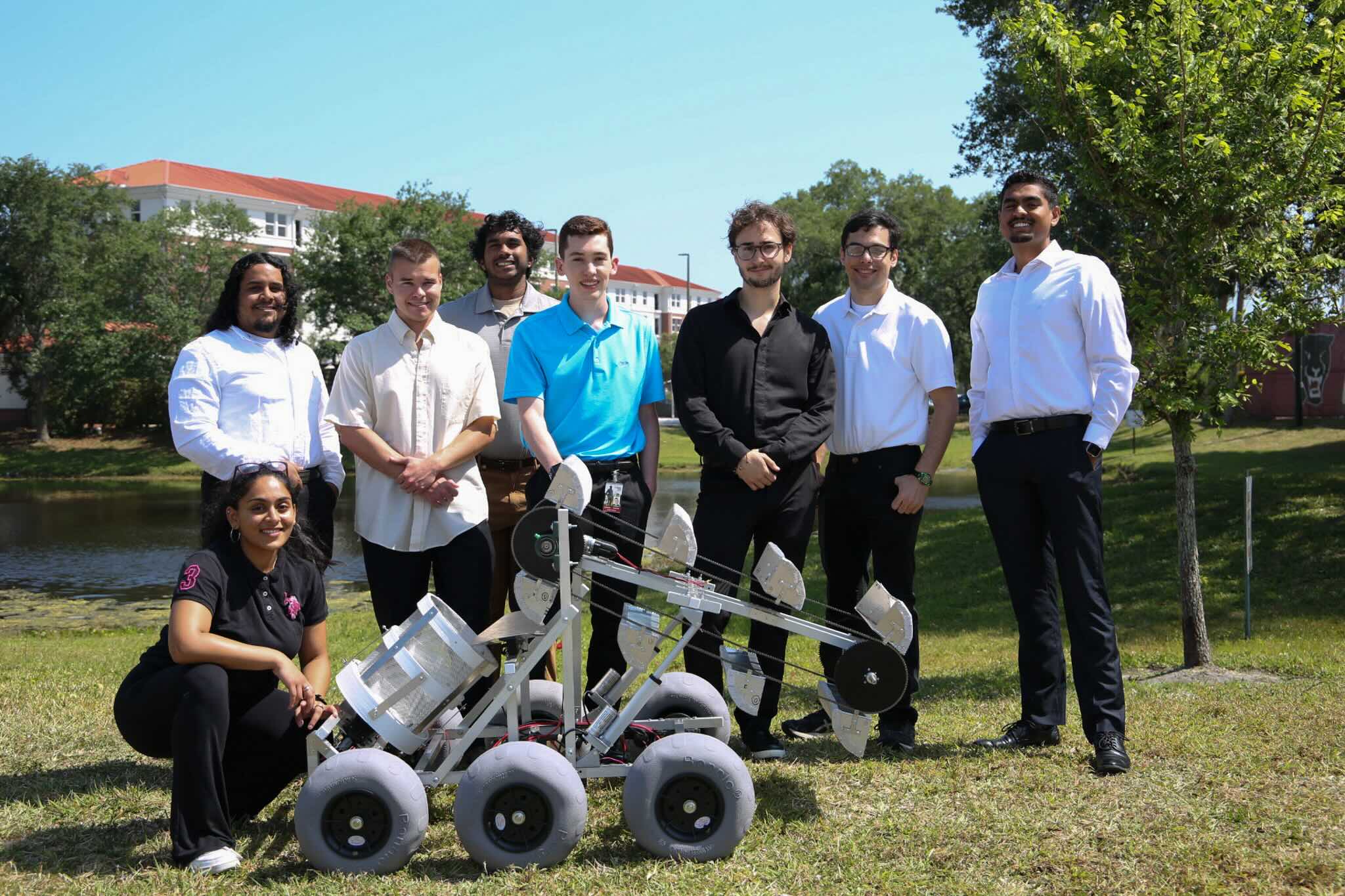
Team Member(s)
Sidney Causey, Shayla Peak, Mohammed Aljameeli, Junot Damen, Izaya Farrar, Eric Moseley, Michael Muller, Liam Sapper, Chelsea Sweeney, Shelsy Toppenberg, Noah Walters
Faculty Advisor
Dr. Chiradeep Sen
Robotic Mining Capstone (RMC) File Download
Project Summary
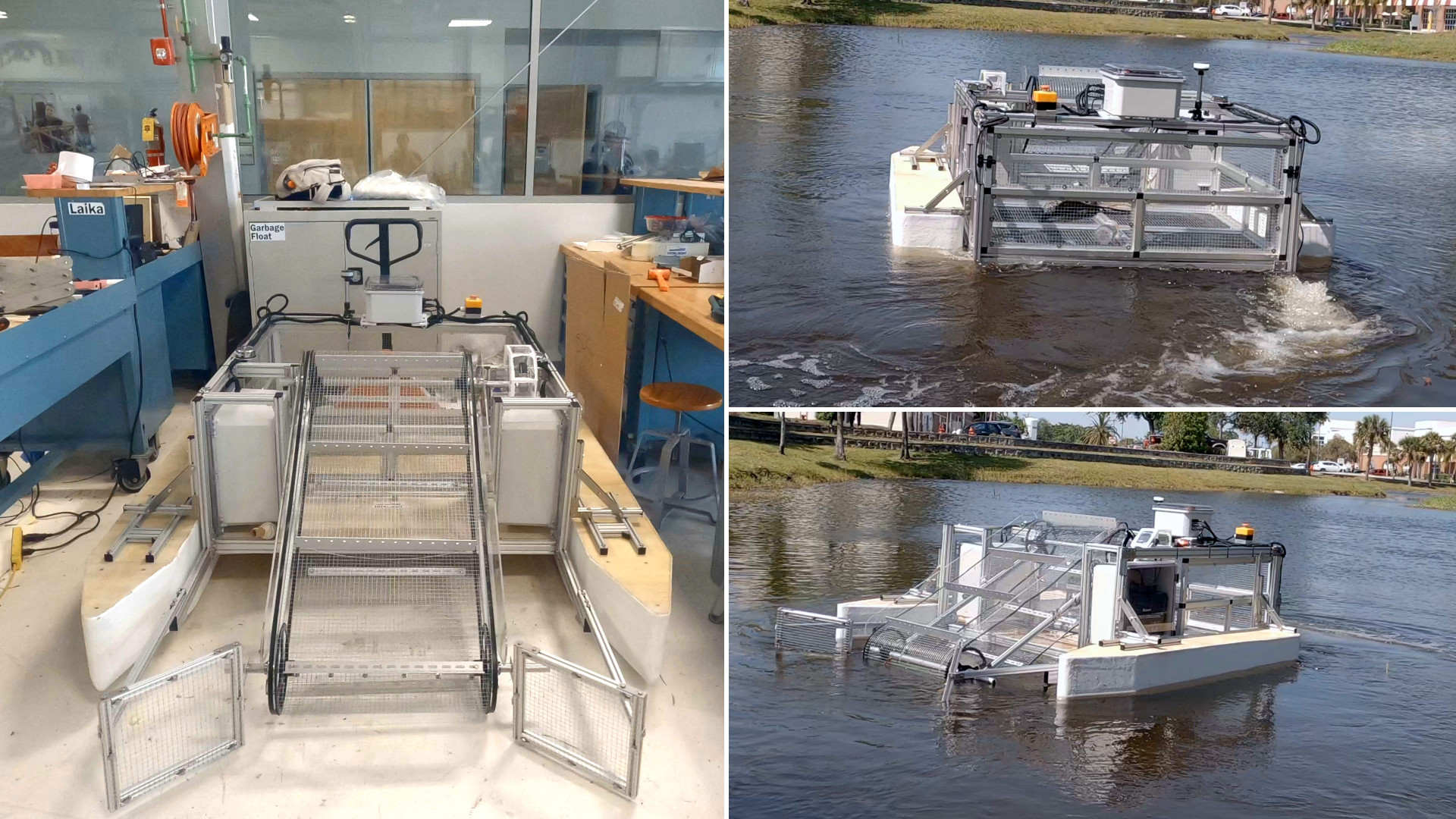
Robotic Mining Capstone (RMC) is a university project in which students must engineer a lunar robot capable of driving, excavating, and constructing a berm designed to shield from radiation, blasts, ejecta, and the harsh space environment. The development of autonomous regolith-handling robots is fundamental for a long-term sustainable human presence on the lunar surface in conjunction with NASA’s Artemis Program. Additionally, the robot’s ability to build berms will protect structures such as astronaut habitats, cryogenic propellant tank farms, and in-situ supplemental food crop centers like NASA’s Veggie Project. RMC’s robot is designed to maximize berm volume relative to size while employing an efficient regolith storage mechanism. Fly ash was used in analog excavation testing to represent the mechanical behavior of lunar maria regolith. To ensure the completion of the robot, engineering design was divided into three subsystems: excavation, structures, and controls.
Project Objective
The principal objective of RMC is to design and manufacture a lunar robot capable of excavating, storing, transporting, and depositing surface-level regolith to build a berm that shall shield critical structures from the harsh space environment. Protecting astronaut infrastructure is essential in developing a sustained off-planet human presence.
Manufacturing Design Methods
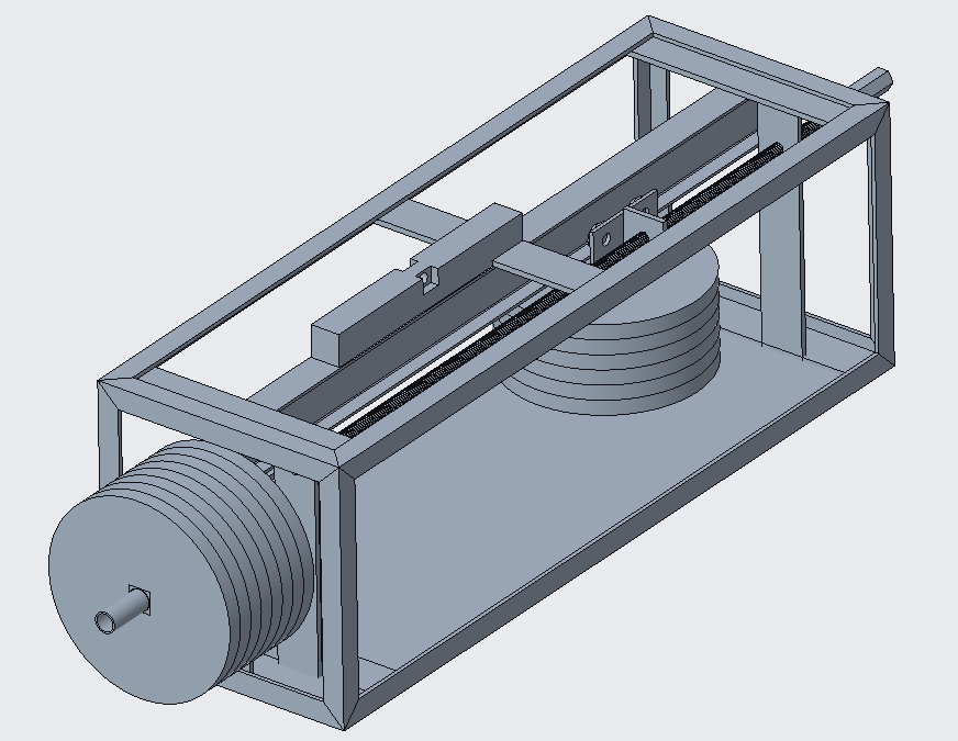
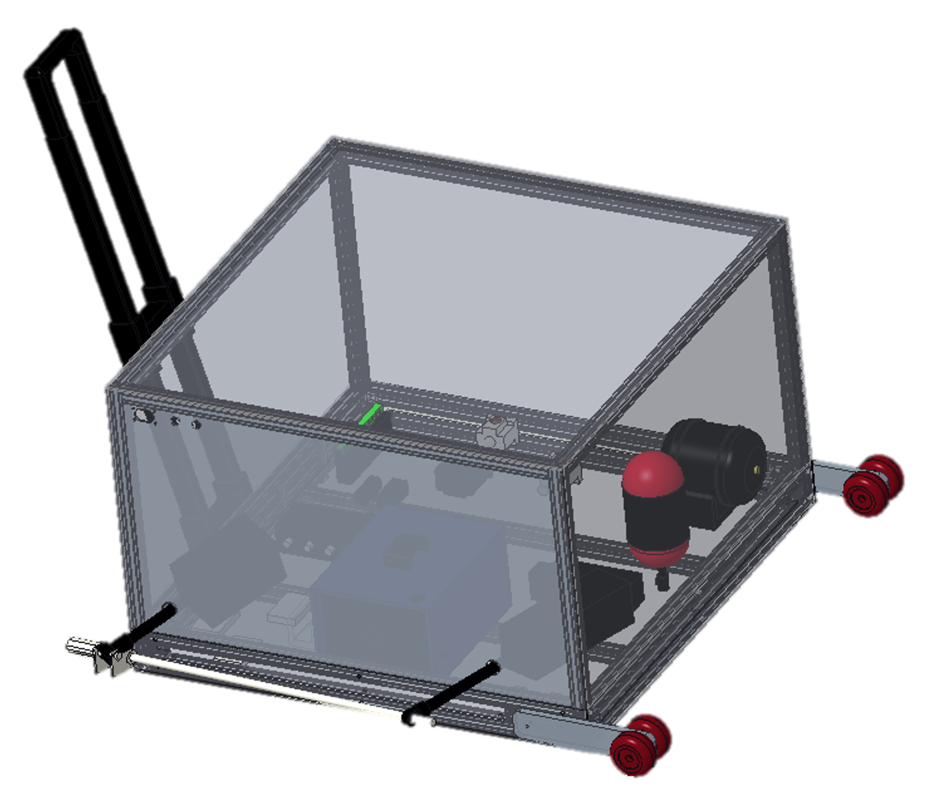
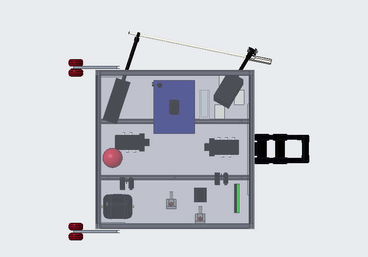
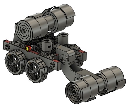
After conducting a thorough literature review of robotic excavation mechanisms, the team opted for a bucket drum design due to its proven success and relative simplicity. The fidelity of this design was validated through Becker 3D® simulations, a software demonstrating regolith particle loading, which yielded the prototype’s fill capacity. The selected bucket drum design was coined “double-double” for its double-scoop double-storage geometry.
For mobility, hollow rigid wheels with grousers were selected to improve traction while minimizing dust buildup. The robot’s wheels were 3D-printed in-house from PLA. Through Ansys® simulations, it was proven that PLA can handle expected torques during digging and driving with a factor of safety of 1.23. The chassis is built from Al 6063, selected for its lightweight and machinability. Passive dust control measures were taken to protect sensitive components during driving and excavating. These include implementing 3D-printed dust covers and plugging exposed holes with putty.
For the controls suite, a Raspberry Pi is utilized for the onboard computer with Python scripting that executes manual and autonomous waypoint navigation sequences. Brushless motors were implemented for their efficiency and longer lifespan. Additional electrical hardware includes a 12V 9Ah lead acid battery, motor controllers, through bore encoders with hall sensors, an IMU, and a COTS kill switch. All electronics are housed within a sealed box to mitigate dust erosion of wiring and sensitive components.
Analysis
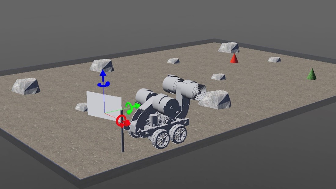
A suite of programs was used to perform a comprehensive analysis of the robot. Torque profiling and stress analysis were conducted using Ansys® for the wheels. The anticipated bending stress on the chassis was determined using a MATLAB® shear-moment script. Webots® was used to create a simulated mission arena with rocks, craters, and mining zones. A mock robot was piloted through this virtual arena to refine the capabilities of the physical prototype. To refine the excavation design, Becker 3D® simulated the regolith particle loading into and out of each bucket drum. This yielded a percent fill capacity (~80% per drum). In addition to the aforementioned programs, first-order calculations were performed by hand and in Python to confirm expected magnitudes.
Future Works
Future work includes refining the robot’s autonomous navigation code and implementing an image path planning algorithm. While the robot is capable of manual control, full autonomy will require additional testing for turn precision, waypoint accuracy, and calibration of the IMU to mitigate sensor drift and system noise. For lunar-based applications, the team envisions the installation of onboard image processing by which the robot can navigate through a local region without dropping waypoints beforehand.
Manufacturing Design Methods
After conducting a thorough literature review of robotic excavation mechanisms, the team opted for a bucket drum design due to its proven success and relative simplicity. The fidelity of this design was validated through Becker 3D® simulations, a software demonstrating regolith particle loading, which yielded the prototype’s fill capacity. The selected bucket drum design was coined “double-double” for its double-scoop double-storage geometry.
For mobility, hollow rigid wheels with grousers were selected to improve traction while minimizing dust buildup. The robot’s wheels were 3D-printed in-house from PLA. Through Ansys® simulations, it was proven that PLA can handle expected torques during digging and driving with a factor of safety of 1.23. The chassis is built from Al 6063, selected for its lightweight and machinability. Passive dust control measures were taken to protect sensitive components during driving and excavating. These include implementing 3D-printed dust covers and plugging exposed holes with putty.
For the controls suite, a Raspberry Pi is utilized for the onboard computer with Python scripting that executes manual and autonomous waypoint navigation sequences. Brushless motors were implemented for their efficiency and longer lifespan. Additional electrical hardware includes a 12V 9Ah lead acid battery, motor controllers, through bore encoders with hall sensors, an IMU, and a COTS kill switch. All electronics are housed within a sealed box to mitigate dust erosion of wiring and sensitive components.