Project Summary
Project AERIS was established to address the growing need for affordable, realistic testing platforms for autonomous satellite servicing and inspection technologies. On-orbit testing of these systems is prohibitively expensive and high-risk, motivating the creation of a ground-based environment where these capabilities can be safely developed and validated. The project also supports the aerospace industry’s push toward autonomous on-orbit operations, which can be helpful for satellite servicing, inspection, and debris mitigation. The Autonomous Experimental Rendezvous and Inspection System is focused on developing a realistic test environment and an autonomous platform to support and validate advanced satellite inspection technologies, rendezvous, and proximity operations (RPO). The system integrates four main elements including a drone-based chaser vehicle with onboard sensors and software, a visually-accurate satellite model mounted on a one-degree-of-freedom (1 DOF) test stand, and a controlled ground environment to emulate space-like conditions. Together, these components form a full testbed for testing and validating deep learning-based computer vision and advanced guidance, navigation, and control (GNC) algorithms. Stakeholders of this project include Dr. Ryan White and Neural Transmissions (NETS) Lab, the Florida Institute of Technology Aerospace Engineering Department, and the College of Engineering and Science, all of whom will benefit from AERIS for future work in autonomous spacecraft operations
Project Objective
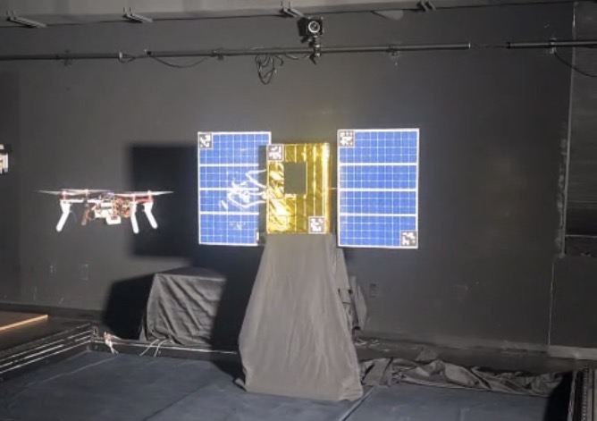
The objective of Project AERIS is to design and implement a system that evaluates the performance of an AI vision algorithm within a space-like environment under representative mission conditions (OBJ.01). The system employs a physical drone to simulate a chaser satellite (OBJ.02), performing stable proximity operations within 25 cm of a representative satellite mock-up (OBJ.03, OBJ.04) to enable realistic inspection scenarios in the Autonomy Lab at Florida Institute of Technology. A motorized test stand with rotational motion about the Z-axis is incorporated to simulate dynamic target behavior and validate tracking performance (OBJ.05). Stationary cameras further enhance the system by providing multi-perspective coverage as a cost-effective alternative to swarm-based sensing (OBJ.06).
Manufacturing Design Methods
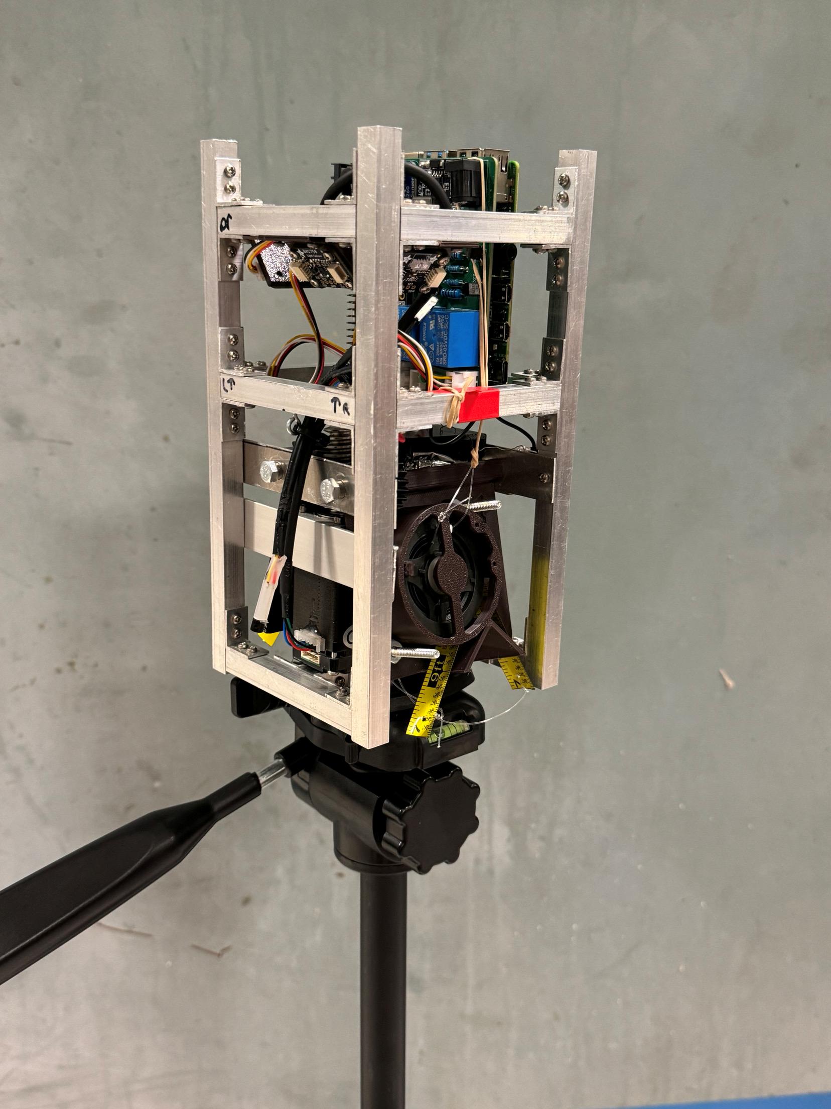
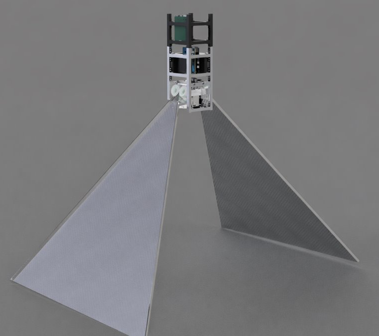
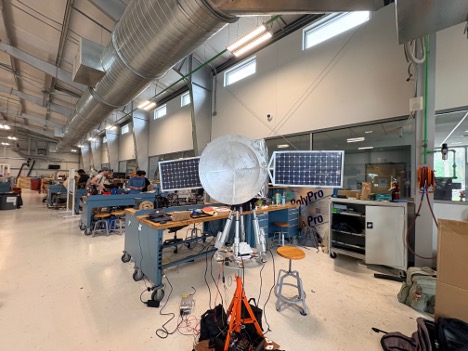
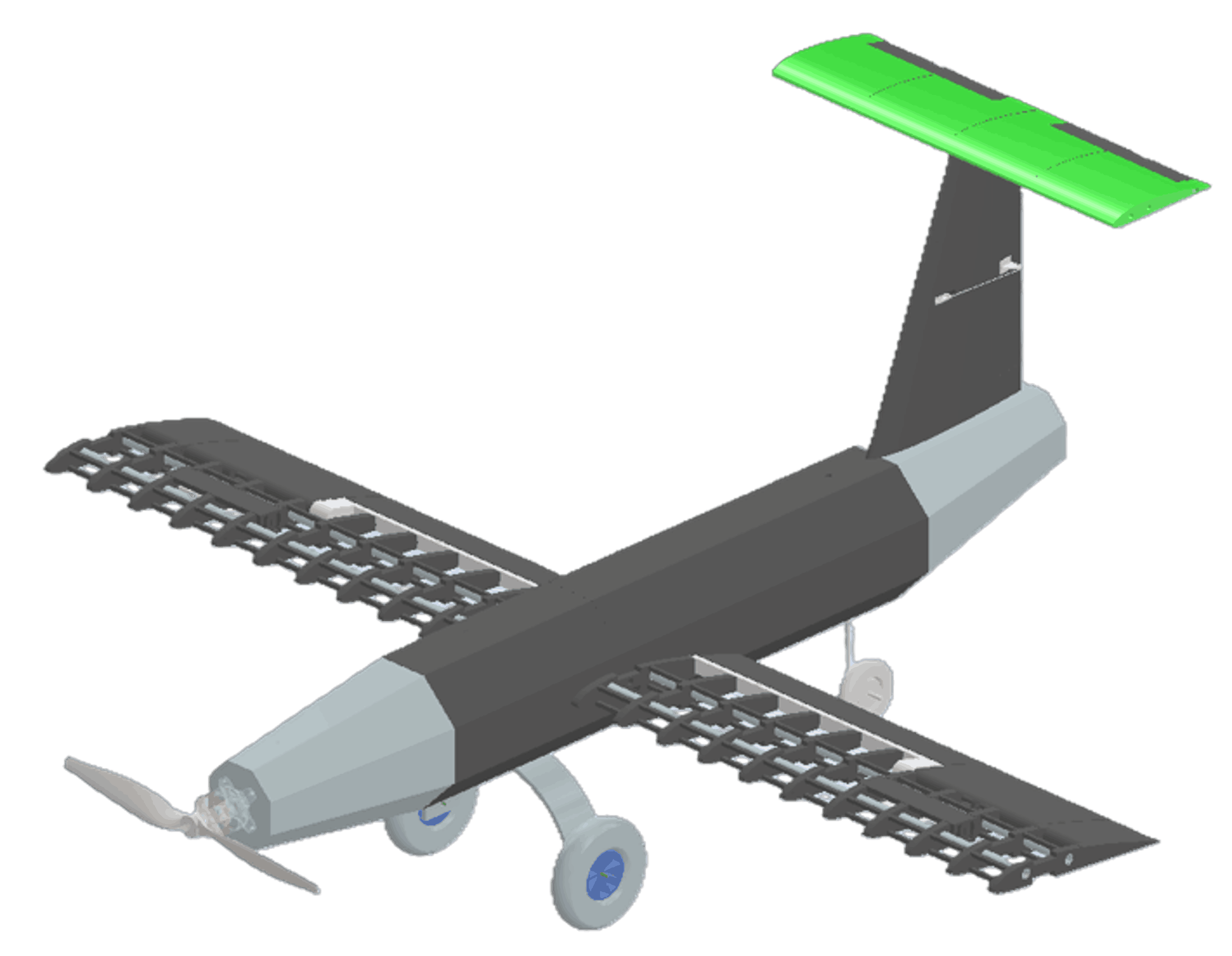
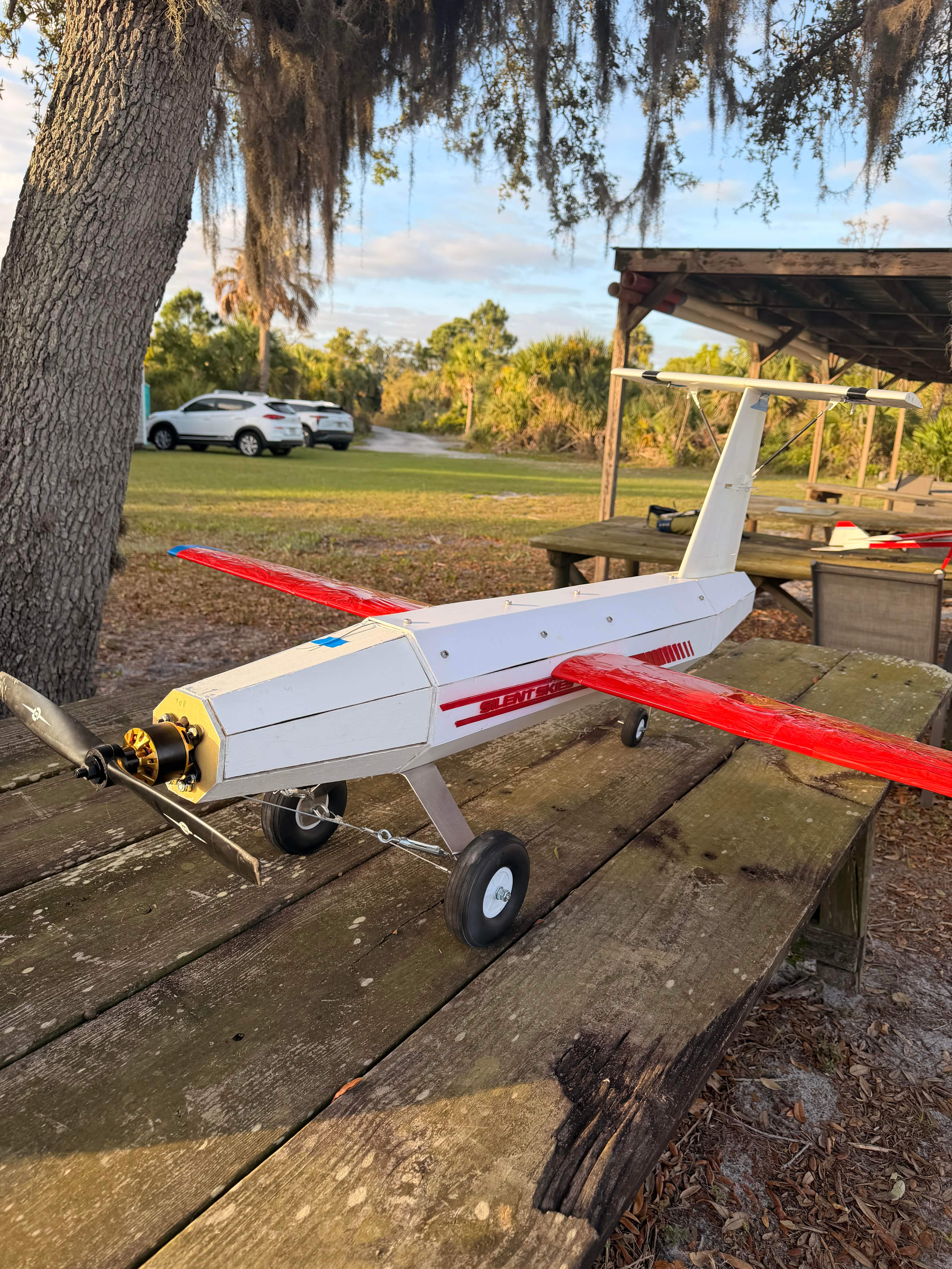
Project AERIS was developed using a design–build–test–refine methodology that integrates analytical modeling with rapid prototyping to create a functional autonomous inspection testbed. The system combines a quadcopter drone, a scaled satellite mockup, a motorized rotating stand, and a controlled testing environment, all designed for modularity and repeatability. Initial designs were created in CAD and validated using MATLAB and ANSYS to estimate structural performance, torque requirements, and system behavior. The drone platform utilizes a commercial frame with custom 3D-printed mounts to integrate onboard computing and vision sensors, enabling real-time detection and navigation. The satellite mockup was fabricated using aluminum and lightweight composite materials to replicate key geometric and visual features while maintaining low mass. The rotating test stand was constructed from aluminum T-slot extrusion with a bearing and geared motor system to provide controlled rotation about a single axis. All components were assembled and iteratively refined through testing to ensure reliable performance and consistent experimental conditions.
Specification
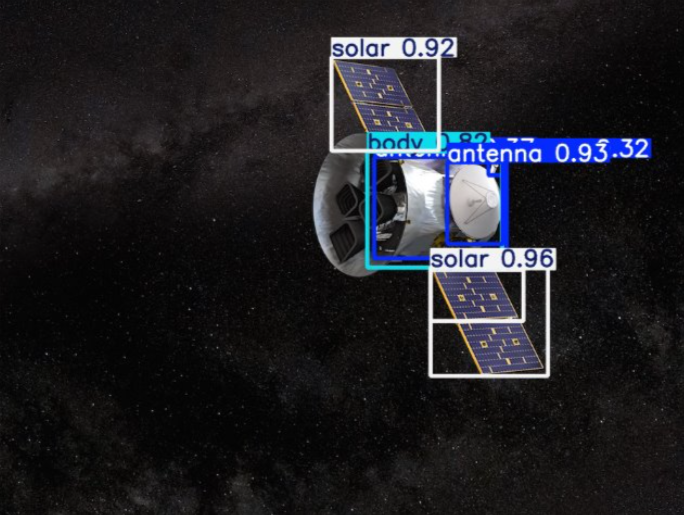
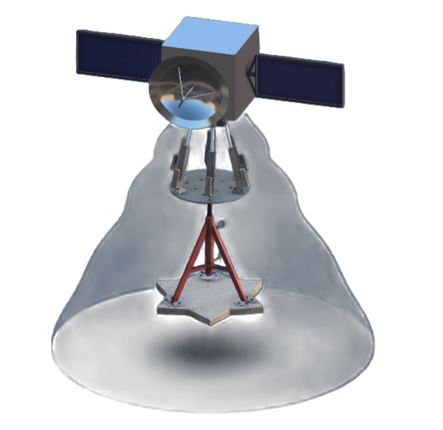
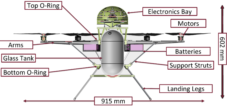
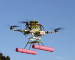
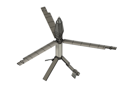
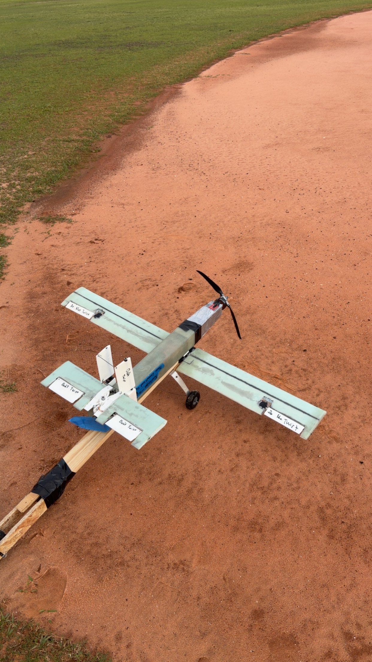
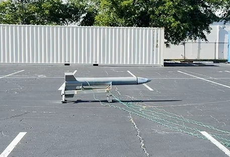
Drone Platform: F450 Quadcopter Frame Kit with Pixhawk Developer Kit flight controller running ArduPilot, integrated onboard computing via NVIDIA Jetson Orin Nano Developer Kit and depth sensing using Intel RealSense D435i with YOLOv5-based vision processing Camera System: Forward-mounted RGB + depth camera configuration for real-time detection and pose estimation Flight Configuration: Quadcopter Dry Weight: ~8–10 lbs Payload Capacity: ~2–4 lbs Thrust-to-Weight Ratio: ~2.5–3.0 Satellite Mockup: Scaled 12U CubeSat-inspired structure Overall Dimensions: ~15 in × 22.5 in body with extended solar arrays (~20 in × 30 in panels) Structural Materials: Aluminum frame with composite paneling Fiducial System: 100 mm ArUco markers distributed across faces and array edges Total Mass: ~15–20 lbs (configurable) Rotating Test Stand: Frame: 1515 aluminum T-slot extrusion (80/20) Bearing System: ~9–10 in lazy Susan bearing with internal track Drive Motor: 270:1 DC geared motor (CQRobot 37mm DC Geared Motor 270:1) Gear Interface: ~20-tooth pinion engaging internal ring track Rotation Axis: Single DoF about vertical (Z-axis) Operational Speed: 2–5 deg/s sustained Positional Accuracy: ±2° Load Capacity: ≥25 lbs top plate Testing Environment: Indoor controlled lab setup (CAMID facility) Lighting Conditions: Consistent diffuse lighting for vision reliability Control System: Arduino-based motor control (Elegoo Uno R3) with L298N driver Endurance Capability: ≥10 minutes continuous operation per test cycle.
Analysis
To validate the structural integrity and dynamic performance of Project AERIS, a combination of analytical modeling and ANSYS Mechanical simulations was conducted to assess system behavior under expected operational loads. The rotating stand and satellite assembly were evaluated for stress distribution, deflection, and torque requirements, with particular focus on critical components such as the bearing interface, motor-driven gear interaction, and primary load-bearing structure. Simulations were performed under static and quasi-dynamic conditions with appropriate boundary conditions and contact definitions to accurately represent real-world behavior. Results indicate that the selected materials and structural configuration maintain sufficient rigidity and remain within allowable stress limits during continuous rotation at target angular velocities. A dynamic analysis was also performed to estimate the system’s mass moment of inertia and corresponding motor torque requirements, confirming that the drive system can achieve and sustain desired rotational speeds without inducing instability or excessive loading. Additionally, the impact of rotational motion on sensor performance was evaluated to ensure angular velocities remain within a range that preserves image clarity and reliable detection for the onboard vision system. In general, these analyses demonstrate that the AERIS platform meets its mechanical and operational requirements, providing a stable and repeatable environment for autonomous inspection testing.
Future Works
Future development of Project AERIS will focus on transitioning the validated vision algorithm from a laboratory environment to an operational spacecraft platform. This includes integrating the algorithm into a real chaser satellite system and adapting it to function under space environment conditions, such as microgravity, orbital dynamics, variable lighting, and radiation effects. Additional work will involve expanding the system to support fully autonomous navigation and inspection, as well as validating performance through higher-fidelity simulations and on-orbit testing. These advancements will bridge the gap between ground-based experimentation and real-world space deployment.
Acknowledgement
Team AERIS would like to thank Dr. Firat Irmak and Dr. White for their guidance and support throughout the duration of this project. The team also acknowledges the Florida Institute of Technology for providing the facilities, resources, and academic environment that made the design, analysis, and testing of the AERIS system possible. Additional thanks are extended to Dr. Tiwari and Prenith at the Autonomy Laboratory for access to their testing environment and facilities. The team is also grateful for the support provided in the Senior Design Laboratory, with special recognition to Felix Gabriel, Zac Schardt, and Royce Jacobs for their assistance during the fabrication and assembly of the AERIS system.

/prod01/fit-cdn-pxl/media/header-images/showcase-header.jpg)


