
/prod01/fit-cdn-pxl/media/header-images/showcase-header.jpg)
Awards 2023
President's Cup
Analysis of NavCam 1 Image Anomalies at Bennu
Team Member(s)
Brooke HurshFaculty Advisor
Dr. Brent J. BosSecondary Faculty Advisor
Dr. Hamid K. RassoulAnalysis of NavCam 1 Image Anomalies at Bennu File Download
Project Summary
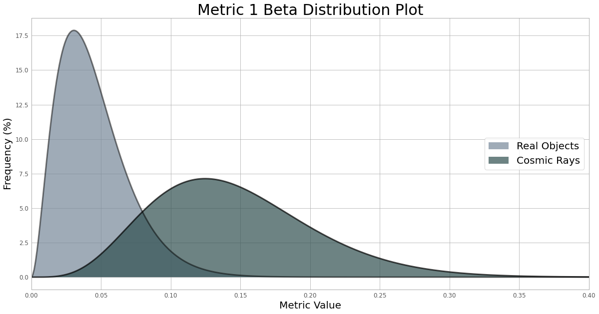
On October 30, 2018, while approaching Bennu, the OSIRIS-REx Touch-And-Go Camera System’s (TAGCAMS) NavCam 1 began acquiring images of Bennu to support optical navigation and orbital maintenance. Some of these images contained anomalies (i.e. image features not caused by known astronomical objects) that were initially attributed to radiation artifacts. These artifacts are instantaneous, occurring in a single image frame. On January 6, 2019, after OSIRIS-REx began orbiting Bennu for the first time, NavCam 1 began observing image anomalies which were visible over multiple image frames. These were determined to be caused by particles ejected from Bennu’s surface. The observation of several more mass particle ejection events allowed for the cataloging of confirmed multi-frame particle streaks, with the intent to determine if qualitative metrics could be used to identify anomalies occurring within a single image frame. A total of 2,148 image anomalies were visually inspected and their basic characteristics were recorded. Due to a dark reference pixel region on NavCam 1 (a pixel region in which light cannot enter the detector), certain image anomaly characteristics were definitively attributed to cosmic rays. After examining 356 confirmed particles which were seen in multiple image frames, certain characteristics were also attributed to real objects. Using these characteristics, we have developed two simple image metrics that discriminate between real objects and radiation artifacts. After a thresholding process, Metric 1 divides the DN of every pixel in the streak by its maximum DN, then takes the standard deviation of those values. The metric value for particles is expected to be lower. Metric 2 takes the fifth highest pixel DN of an anomaly and divides it by the maximum DN of the anomaly. For particles, this metric value is expected to be close to 1. A beta distribution was fit to each histogram of the metric values. These metrics allow us to estimate the probability of an image anomaly being caused by a real object. If unresolved streaks are observed in single image frames during future missions which use the same detector as TAGCAMS, these metrics may be applied to determine if the streaks are real objects or radiation artifacts. This includes the Lucy mission, a mission to the near-Earth asteroid Apophis using the OSIRIS-REx spacecraft, and the Mars Sample Return Mission.Project Objective
The first objective was to catalog image anomalies in images taken by NavCam 1, then determine if qualitative metrics could be used to identify a single frame anomaly as a particle or radiation artifact. The second objective was to create the qualitative metrics capable of distinguishing particles and radiation artifacts.Analysis
We have developed two simple image metrics that discriminate between real objects and cosmic rays by considering an anomaly’s intensity variation. Both metrics ignore saturated pixels. For Metric 1, any pixel whose digital number (DN) is less than the mean and 1.5 standard deviations is not processed. After thresholding, this metric divides the DN of every pixel in the streak by its maximum DN, then takes the standard deviation of those values. The metric value for particles is expected to be lower. For Metric 2, the thresholding process excludes any pixel whose DN is less than 1.25 times the mean and the standard deviation. Then, the metric takes the fifth highest pixel DN of an anomaly and divides it by the maximum DN of the anomaly. For particles, this metric value is expected to be close to 1. A beta distribution was fit to the histograms of both metric values.Future Works
If unresolved streaks are observed in single image frames during future missions which use the same detector as TAGCAMS, these metrics may be applied to determine if the streaks are real objects or radiation artifacts. This includes the Lucy mission, a mission to the near-Earth asteroid Apophis using the OSIRIS-REx spacecraft, and the Mars Sample Return Mission.Acknowledgement
I would like to acknowledge the OSIRIS-REx team and NASA Goddard Spaceflight Center for hosting this research. Additionally, I owe many thanks to my mentor, Dr. Brent J. Bos, for his support of this work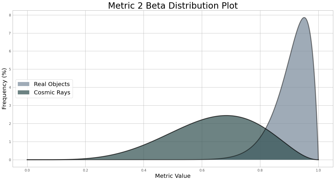
R3MORA
Team Leader(s)
Parker BaillonTeam Member(s)
Suzie Dixon, Katlynd Faust, Payton Herman, Harpoon SeabringFaculty Advisor
Dr. Stephen WoodSecondary Faculty Advisor
Dr. Ronnal ReichardR3MORA File Download
Project Summary
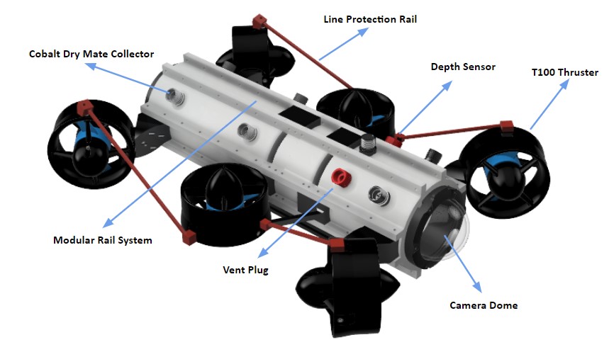
Project R3MORA (Resin 3D Printed Marine Operable Research Assistant) is a multi-stage project. The first portion of this project developed a complete set of material properties for three different Siraya Tech Stereolithography (SLA) 3D printing resins. This portion of the project was published at the Ocean Hampton Roads Conference 2022 and was well received. Printing pressure enclosures greatly reduces cost and creates many possibilities for customization. Based on the data and techniques published, many parties have shown interest in adopting the process for low-cost student design competitions. In addition to the competition groups, the resin pressure enclosures are also being utilized for biofouling control testing at Port Canaveral. The second portion designed and produced a small, diver-deployable, remotely-operated vehicle (ROV) printed using the materials tested during stage one. A variety of goals can be completed with the R3MORA vehicle, and many of them apply to the average recreational diver. Using R3MORA, divers who are not certified for cave exploration or internal spaces in shipwrecks, for example, may gain access to these places that they normally could not explore. Divers who operate the R3MORA also increase their access to unique footage or photography capabilities. Furthermore, the R3MORA vehicle can increase the general safety of the diver as it would provide situational awareness through the video stream. It could also be utilized to help locate a missing diver or item in an unsafe situation. It would fill a public safety niche within the diving community, thus having a positive societal impact.Project Objective
1) Develop a set of ASTM material properties for Siraya Tech SLA 3D printed resins. 2) Design a 3D-printed pressure enclosure for a small, diver-deployable ROV. 3) Design and build a functional prototype of the diver-deployable ROVManufacturing Design Methods
Project R3MORA was manufactured from all 3D printed parts. This kept costs low and allows the project to be open source so the barrier to entry to an ROV can now be greatly reduced.Specification
Depth Rating: 400ft Endurance: 2hrs Sensors: Temperature and Depth HD Camera Modular expansion ports 6 Motors 6 Degree of FreedomAnalysis
Design work was completed with Fusion 360. The built-in NASTRAN FEA solver was used for the analysis of the pressure enclosures. Material testing data from the Universal Testing Machine was processed with MATLAB.Future Works
Publication of Vehicle Design paper in Oceans 2023 Conference Mississippi Development of Underwater controller and tether management system Testing of long-term exposure of pressure enclosures for other oceanographic projectsAcknowledgement
We would like to thank all those involved in the Underwater Technology Lab, Structural Composites, Inc., and the Center for Corrosion and Biofouling Control for continuously lending their knowledge and support. Without any of the parties listed above R3MORA would not have been possible.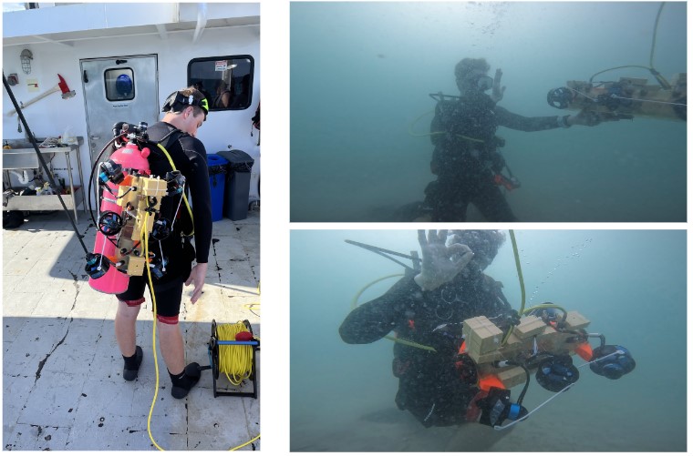
Northrop Grumman Best in Show Awards
Electrostatic Dust Lofting: A Possible Cause for Beam Losses at CERN’s LHC
Team Member(s)
Amanda ElliottFaculty Advisor
Dr. Paul MartinSecondary Faculty Advisor
Dr. Hamid K. RassoulElectrostatic Dust Lofting: A Possible Cause for Beam Losses at CERN’s LHC File Download
Project Summary
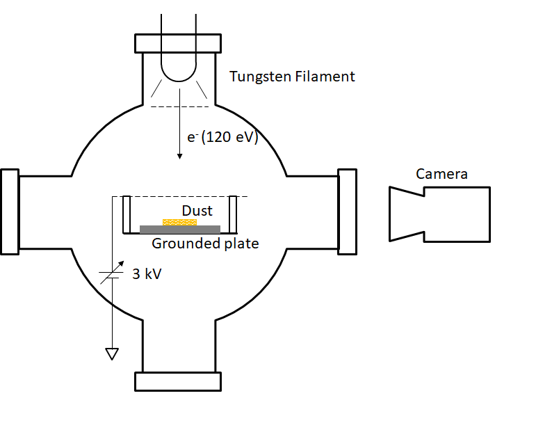
Dust particles interacting with the proton beams have caused thousands of beam-loss events at CERN’s Large Hadron Collider (LHC), some of which led to premature beam dumps and even magnet quenches, frequently resulting in day-long shutdowns. It has been hypothesized that dust particles on the vacuum chamber wall of the LHC become negatively charged due to electron clouds and can detach from the chamber wall by the electric field of the beam. To test this hypothesis, we performed experiments in a vacuum chamber to study the electrostatic lofting of dust particles from conducting surfaces. First, a monolayer of dust (silica,Project Objective
To test this hypothesis, we designed and performed experiments in a vacuum chamber to study the electrostatic lofting of dust particles from a conducting surface. Dust charging and high voltage lofting experiments are performed, and the resulting dust movement is recorded using a high-speed camera. The properties of dust charging and levitation are characterized from these videos. In order to achieve the long-term goal of dust mitigation in the LHC, we must first understand the relevant parameters that facilitate dust lofting.Analysis
The properties of dust charging and levitation are characterized from recorded high-speed videos. Scripts were developed to process these videos. The common algorithms for these scripts include lofted particle detection, multiple particle tracking, size calculation using a Flood Fill algorithm, particle velocity and acceleration calculations, and correction for the camera angle relative to the dust sample. Different calculations are performed depending on whether the dust grains lofted during high voltage (vertical trajectories) or during charging (parabolic trajectories). Additional calculations are performed for dust grain surface potential, charge, and lofted angle using QR Factorization.Future Works
Experiments are ongoing at the University of Colorado, Boulder, with the goal of better replicating LHC conditions using sudden impulse charging and high voltage application. It is also important to note that dust in the LHC experiences charging (from synchrotron radiation) and high voltage simultaneously, while we have only tested charging and high voltage applications separately. Data has been collected from charging using an UV lamp and high voltage application simultaneously, and is in the process of being analyzed.Other Information
This research is being presented at a poster session at the International Particle Accelerator Conference (IPAC) in Venice, Italy on May 7-12, 2023, by one of our CERN collaborator's, Rudiger Schmidt.Acknowledgement
Experiments are performed under the advisement of Xu Wang and Mihály Horányi at the Institute for Modeling Plasma, Atmospheres, and Cosmic Dust (IMPACT), at the University of Colorado, Boulder. This project is an ongoing collaboration with the following CERN researchers: Rudiger Schmidt, Daniel Wollmann, Christoph Wiesner, and Philippe Belanger. This research was funded by NSF’s physics Research Experience for Undergraduates (REU) program.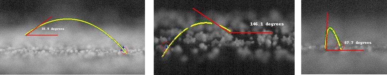
BiPROP Rocket Competition Team
Team Leader(s)
Project Manager: Emma Brackett, Systems Engineer: Craig BosworthTeam Member(s)
Craig Bosworth, Emma Brackett, Hannah Bryant, Tyler Bullock, Nathan Cerletty, Andrew Ivarson, Brian Lopes, Christopher Mickel, Aidan O'Connor, Jacob Smith, Ashley TisaranniFaculty Advisor
Daniel KirkSecondary Faculty Advisor
Douglas WillardBiPROP Rocket Competition Team File Download
Project Summary
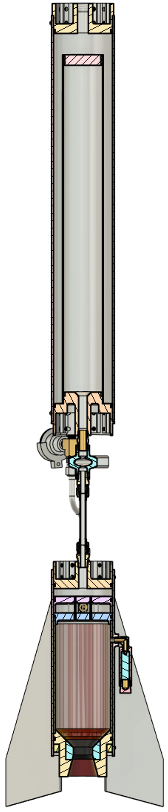
BiPROP is a student-designed and manufactured liquid bi-propellant rocket that is tasked with the challenge of reaching an exact altitude of 5,000 feet. The rocket will compete in the Friends of Amateur Rocketry (FAR) Competition in the Mojave Desert. To ensure all elements of the rocket vehicle are accounted for, the team was split into six subsystems: Chamber/Injector/Nozzle, Fluid Systems, Structures, Avionics/Recovery, Ground Systems, and Safety. The main objective of BiPROP is to launch and safely recover a liquid bipropellant rocket and carry a payload of at least 1 kg that transmits and records live video of the flight. From this project objective, a design of the rocket vehicle was made, which includes an overall 4-inch diameter and approximately a height of 8 feet. A thrust of 500 pounds was determined to reach the needed altitude and will be achieved using Nitrous Oxide and Isopropyl Alcohol as oxidizer and fuel respectively. A two-stage recovery system will be utilized per competition rules, as well as an altimeter/GPS to determine the altitude. After the analysis was performed to ensure the rocket design was optimal for the set requirements, the creation of models and manufacturing began. The team utilized Fusion 360 as the main modeling software, due to its ability to allow for collaboration between multiple members on one part of the rocket. As for the analysis, the majority was done by hand using knowledge gained through the team's experience in the classroom over the last four years. Though some parts were bought commercially off the shelf, most of the rocket was manufactured in the university’s machine shop and design center. To ensure the design met the main requirement of the project, which was to launch a rocket to 5,000 feet, several tests were carried out. For the fluid systems, many of the valves were manufactured in-house. So, pipe loss tests were carried out to ensure the valves not only worked but did not decrease the mass flow of the propellants significantly. Per competition rules a hydrostatic test of the propellant tank had to be carried out, this was done with help from two other Senior Capstone projects, META Controls, and Test Stand. The main test that needed to occur was the static test fire, however before that was completed a cold flow test was needed to ensure the co-axial shear injector design is operating properly. Both tests were performed on the same day and utilized the help of the teams mentioned before. At the conclusion of this project, BiPROP was able to successfully design and manufacture a liquid bipropellant rocket that will hopefully prove to reach 5,000 feet in June of this year. The results from this project will help inspire future years of liquid bipropellant rocket designs as this project continues. The failures and setbacks faced by this year's team not only acted as learning experiences for the current members but also for future members to come.Manufacturing Design Methods
In general, most components and subsystems will be built from the ground up. Collaboration with the Harris Student Design Center (HSDC) and machine shop leadership and facilities will be critical for the successful construction of the bipropellant rocket. Many parts will need to be machined in person which will require use of the manual and CNC machinery (i.e.: lathe, mills, welding) provided in both locations. While official operation of the rocket would be in an acceptable outdoor environment with the META test stand, assembly and installation of the rocket subsystems can be conducted at the reserved bench for the BiPROP team in the HSDC.Analysis
In general, the team will use accepted industry methods (hand calculations, simulation tools, custom simulation codes, etc.) to compare different design approaches that satisfy the project requirements. Design solutions for the rocket and each subsystem will be selected based on their safety to personnel and equipment, feasibility, and cost. The team will use calculated and simulated results to design the rocket. Each subsystem or component will be tested to verify design works.Future Works
The continuation of BiPROP will provide a new team of students the opportunity to investigate a variety of things including, but not limited to: Extended failure mode analysis, Performance enhancements, Digital analysis comparison, Advanced payload integration, and Improved manufacturing methods.Acknowledgement
We would like to give a huge thank you to Christopher Napoli, Victor Manuel Bautista Katsalukha, Dr. Daniel Kirk, Dr. Darshan Pahinkar, and Dr. Douglas Willard for their continued support with BiPROP. Their guidance was invaluable to the progression and learning experiences of this project.Honors College Award
ExoArm

Team Leader(s)
Samantha SequeiraTeam Member(s)
Holly Grant, Catrina McCoy, Mohammed Fahad M Aba AlkhaylFaculty Advisor
Dr. Keshav ChivukulaSecondary Faculty Advisor
Dr. WhiteProject Summary
Hundreds of thousands of people have conditions that affect their upper body movement, ranging from cerebral palsy to stroke rehabilitation patients to patients who had been in accidents that affected their upper extremities. This causes a disconnect between the patient's mind and body, which is extremely detrimental to the patient's mental health. The ExoArm is a myoelectric exoskeleton arm brace that utilizes an EMG sensor to collect the electrical signals from the arm muscles to control motors that move the brace to mimic the arm's movement. By using the patients' muscle signals to control the brace, the ExoArm is designed to be an extension of the arm that amplifies the patients' strength. The ExoArm uses machine learning to classify the motions of the patient's arm to accurately and quickly convert it into mechanical motion in the brace.Project Objective
The objective of the ExoArm was to design and manufacture a myoelectric exoskeleton brace that amplifies a patient's arm strength to enable them to regain a full range of motion. The ExoArm sought to be completely customizable- from the setup code for the brace's movement so it is specified to its user to the brace's length. This brace aims to be comfortable enough for all-day wear and have all components completely wearable, without the need to be plugged in during use. Another goal of the ExoArm was to minimize the timing delay from the muscle activation to the brace's movement.Manufacturing Design Methods
During the hardware testing stages, an initial design for the brace with drafted with consideration of the weight requirements, mobility, and comfort. The iterated designs were 3D printed and assembled for further structural integrity testing. The design cycled through multiple models; the most significant changes being to the hand to enable the patient to grip and to the elbow to ensure comfort and optimize the range of motion. The hand mechanism was altered so that the movement of the fingers was controlled by the wrist so that patients who have lost fine motor skills can regain their grip strength. During software testing, EMG data was collected from several participants to determine the patterns in the signal, and different methods were tested to determine the best signal-to-motion classification system. In the end, the brace will use machine learning to identify the motion from the signal and output a position to the brace. The brace is similar to some devices that are already on the market and FDA-approved, so our product is predicted to have high success with the various improvements made. The design was predominantly 3D printed for cost-effectiveness and customizability.Specification
The specifications for this project include: being able to lift 50 pounds, having a less than 1-second delay between muscle and brace movement, being comfortable for long-term wear, being customizable for different patients, having a 160º range of motion, having accurate movements from the muscle signal data from EMG sensor, having an entirely wearable design, being more affordable than the competition, and having a lightweight design.Analysis
The data analysis for the hardware was predominantly trying to simulate how the brace would be used in day-to-day life and determine what improvements would be necessary. With each adjustment and improvement to the design, force calculations, biomechanical motion range, and functionality of the user had to be re-examined. For the software, data analysis consisted of determining the best sensor type and placement, understanding the patterns of the EMG waveforms for different motions, and extracting features that have the most correlation to motion. A process of trial and error and visual patterns was used to determine the thresholds of the different features. The movement of the brace, as controlled by the code, was compared against a protractor to ensure the theoretical and actual movements were equivalent. Later, a position sensor was used to record real-time data while also getting the angle of the arm. This data was put into a machine learning model to test the accuracy of classification using XGBoost. With two motions, the accuracy of the predicted motion was 86%, while the accuracy with three motions was 77%. Feature Importance in machine learning was also used to determine the significance of the selected features to the motion results. Through this, it was determined that the bicep muscle was more significant than the tricep, and all features used had high correlations to the motion of the arm.Future Works
Throughout our research and manufacturing process, we developed several different designs to improve functionality. In the future, several improvements could be made to the current design to better assist patients in day-to-day life. For software, advancing the machine learning algorithm will make the responses faster and more accurate. Additionally, including rehabilitation features to simulate a therapy session could aid in patients' recovery. Creating a Bluetooth connection and app would make the brace smarter and easier to use. For hardware, designing the brace to have more adjustable settings would make the brace more inclusive for all ages. Choosing more optimal biomaterials for the brace would increase its integrity and durability.Other Information
Since the inception of the project, the ExoArm team has had a donation link for the cerebral palsy foundation and has raised over 400 dollars toward cerebral palsy research. Watch our Project Video: https://youtu.be/dXDNjwDAp0sAcknowledgement
The ExoArm team would like to thank Dr. Keshav Chivukula for his continual help and advice on this project. The ExoArm team would also like to thank Dr. White for his assistance to the software team with the machine learning code. Additionally, the ExoArm would like to thank Dr. Brenner for his help and support throughout the duration of the project.Best in Show Awards
Research on Methods to Decrease Emissions in Jet Engines
Team Leader(s)
Rebecca Palmer, David Mooney, Brandon NaumannTeam Member(s)
Rebecca Palmer, David Mooney, Shane Webb, Caleb Webb, Zac Davenport, Brandon Naumann, Wenxi LiuFaculty Advisor
Dr. Doug WillardSecondary Faculty Advisor
Dr. Darshan PahinkarResearch on Methods to Decrease Emissions in Jet Engines File Download
Project Summary
The Biofuel Senior Design project aimed to research and develop methods for decreasing emissions on jet engines without compromising engine performance. To solve this problem, these emissions decreases can be accomplished through a combination of a post-combustion carbon capture system utilizing carbonate looping to decrease Carbon Dioxide (CO2) and a Jet-A/Ethanol Biofuel mixture which produces less Nitrogen Oxides (NOx) during combustion.Project Objective
The objective of the project is to decrease NOx and CO2 emissions by some empirically significant amount with minimal performance losses. This project intends to be a proof of concept for these emission mitigation methods.Manufacturing Design Methods
The design portion consisted mostly of extensive research into these topics followed by the creation of something that could feasibly be created in this environment and still work chemically. The biggest challenges we faced were: The budget, temperature requirements, and access to data acquisition tools. Due to a lack of funds, we were forced to redesign and simplify the carbon capture and heat transfer systems. In addition, the lack of funds limited our choice of resilient materials and data acquisition tools, which caused numerous redesigns of the systems and testing plans. As a solution, we will be using an on-campus facility for testing the gas samples and Larsen Industries’ performance sensors.Specification
The exhaust and carbon capture portions were designed to these specifications, to both withstand and utilize the extreme conditions of jet exhaust (~650°C). The Carbon Capture pipe system is made of 304 Stainless Steel, which has advantages including High melting point, availability, low cost, and rigidity. For this project, Calcium Carbonate Looping was chosen which uses the high temperature of the exhaust to convert Carbon Dioxide into a stable Calcium compound. The calcium oxide is introduced into the flow where it reacts and bonds with the carbon dioxide at high temperate. The biofuel was created to alter the chemical composition of Jet-A fuel. Jet A is comprised of Kerosene-hydrodesulfurized & Kerosene (petroleum), which alters its chemical properties by increasing NOx. To reduce NOx, a 20% alteration (B20) is needed.Analysis
From our tests we had two samples that needed further analysis to give us useful results, our exhaust gas and the Calcium Oxide (CaO) which should have turned into Calcium carbonate (CaCO3). For the CaO, we used an Electron Scanning Microscope (ESM) to confirm that the CaO did react with the Carbon in the exhaust gas to form CaCO3 and determine how much of the sample fully reacted. A Real Time Gas Analyzer (RTGA) was used to detect CO2; however, this RTGA was unable to detect NOx, so the NOx concentration will be estimated using CO2.and NOx relations. The CO2 values obtained allow us to directly compare the CO2 output of Jet A, Jet A with Carbon Capture, and our experimental Biofuel with Carbon Capture. Sensors on the test cell also provide temperature and pressure in various locations of the engine as well as fuel flow rate, which allow us to calculate the overall engine efficiency in the 3 different experiments listed above.Future Works
As this project mainly served as a proof of concept for Carbonate Looping, future work would include the construction and testing of a full-sized system including a Carbonator and Calciner. Further research would need to be done to ensure full “looping” could be achieved on a jet engine as only the initial carbon capture using CaO was explored. It would also involve investigating more advanced biofuel mixtures to increase effects, such as the addition of a catalyst to help reduce initial Carbon emissions and the long-term effects of such a biofuel mixture on the internal components of an engine.Acknowledgement
Acknowledgment is given to Larsen Industries, who donated a lot of goods and without whose facilities and support this project would not have been possible. We'd also like to acknowledge Dr. Pahinkar who's knowledge and support was instrumental in the design of this project.Echolynx
Team Leader(s)
Benjamin DiazTeam Member(s)
Benjamin Diaz, Rachel Lee, Luis Cuadros Lamas, Catherine Caicedo, Autumn MonseesFaculty Advisor
Dr. Venkat K. ChivukulaEcholynx File Download
Project Summary
The Echolynx device is developed to address many issues with the current electrolarynx devices on the market. Echolynx provides users with a hands-free device and a Bluetooth controller with dynamic pitch controls along with a reduction in excess noise. These device functions are validated through a series of tests including preliminary functionality tests, direct Echolynx user experiences, and an audibility and intelligibility study. Future improvements to the device include a reduced device size to increase the user’s comfort and improvements in manufacturing.Project Objective
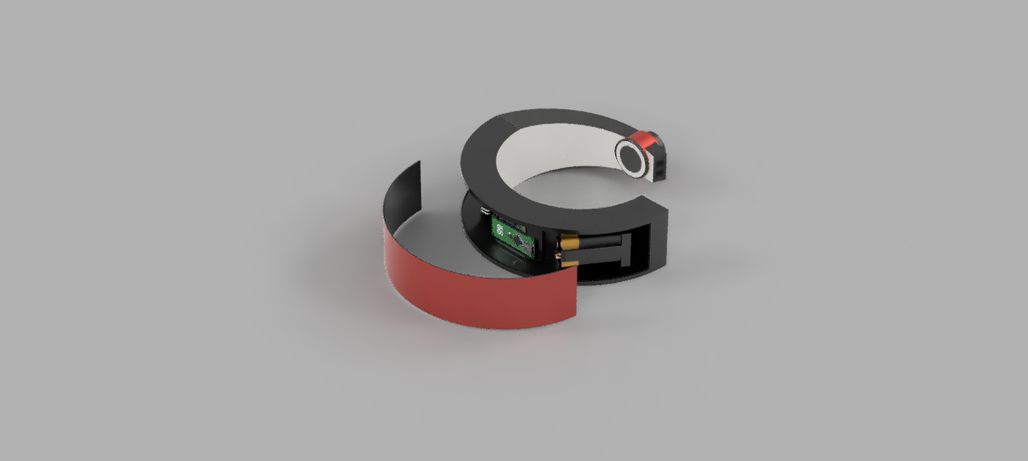
The main struggle of current electrolarynx devices is the excess external noise that masks the user's voice. Electrolarynx devices must be held against the user’s neck while holding down the volume controls, which limits the use of their hands. Another struggle includes the difficulty of making real-time pitch and volume adjustments due to the clunky design. Echolynx addresses these issues by introducing a hands-free model with vibrational insulation and dynamic controls.Manufacturing Design Methods
The vibrational unit is designed to rest around the user’s neck like a collar. The unit will be controlled via Bluetooth connection with the controller. The volume and pitch input variations from the wrist controller directly adjust the vibrational unit through frequency and amplitude shifts of the motor. The vibrational unit is sufficiently insulated by internal silicone coatings and external cushioning materials. Device functionality tests such as vibration permeability tests are completed to ensure the necessary vibrations are achieved and comparison tests with an algorithm are used to validate the vocal accuracy of the user. First-hand user experience tests are used to gain feedback on the true functionality of the device through user testing and user intelligibility.Analysis
After gathering insight from the intelligibility, vocal accuracy, and user experience tests the data will be analyzed and cross-examined to determine the actual functionality of the device. This analysis will provide an understanding of the long-term viability of the device along with areas of improvement when compared to current electrolarynx devices. Audibility is assessed through the listener study portion when the data are statistically compared.Future Works
The Echolynx device can be further developed by improving the range of motion of the user by reducing the size along with a more streamlined manufacturing process.Acknowledgement
Dr. Venkat K. Chivukula, L3 Harris Design Center, Moffitt Health Center.Effects of Microtubule Stability on Mechanosensory Neuron Morphology in C. elegans
Team Leader(s)
Caylin LepakTeam Member(s)
Caylin Lepak, Lillian BeaversFaculty Advisor
Melissa BorgenEffects of Microtubule Stability on Mechanosensory Neuron Morphology in C. elegans File Download
Project Summary
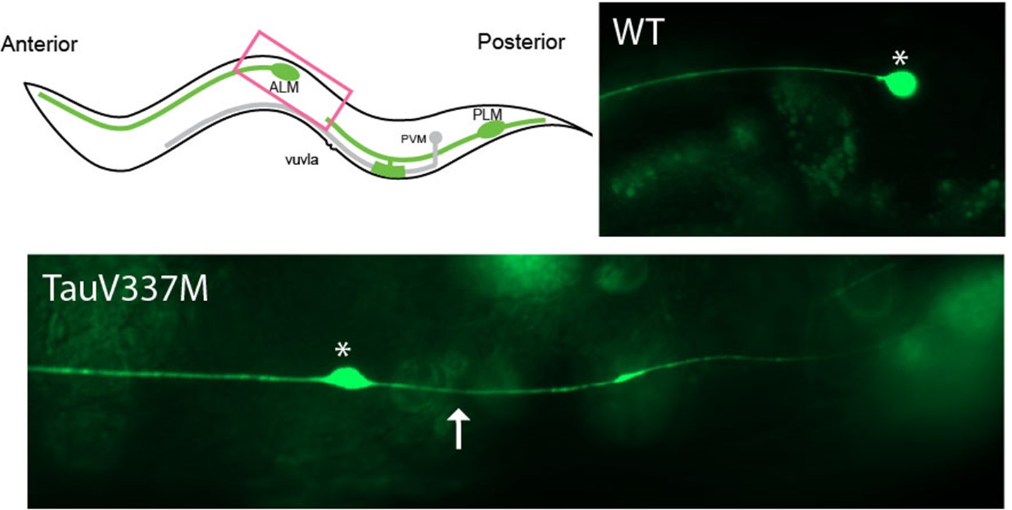
Mechanosensory neurons are responsible for sensing touch, relaying mechanical force into electrical signals. Critical to the function of these neurons are microtubules, which are involved in touch detection and act as the support system of the long axons of these cells. Destabilization of microtubules is linked to several neurodevelopmental and neurodegenerative diseases, but the cellular, genetic, and molecular mechanisms involved are not well understood. Tau, a protein expressed in the nervous system, functions to help stabilize microtubules. A specific mutation of the Tau gene, TauV337M, causes familial Frontotemporal Dementia. Aggregation of Tau forms neurofibrillary tangles, but this is a late-stage disease symptom. Understanding Tau’s role in neurons, and how mutations affect Tau’s functions, will be important throughout life, including development. Uncovering the genetic pathways involved in the complex process of neuronal development will be important for future diagnostics and therapeutic treatments. This study proposes to examine two questions by assessing the morphology of C. elegans ALM neurons: 1) How does the disease-associated TauV337M affect microtubule stability during neuronal development? and 2) What genes does Tau interact with to affect these processes? Using combinatorial genetics, pharmacology, and fluorescence microscopy, we show that the TauV337M mutation causes ALM mechanosensory neurons to grow an ectopic neurite (Fig. 1), which is linked to reduction in microtubule stability. Unexpectedly, we show that strongly reducing microtubule stability through pharmacological manipulation completely prevents formation of the defect. We also show that the ubiquitin ligase, rpm-1, functions downstream of Tau to regulate the development of the ectopic neurite. These results reveal a new genetic pathway between Tau and rpm-1 that provides potential targets for therapeutics for neurodevelopmental disorders and neurodegenerative diseases. This project was partially supported by the Beta Beta Beta Research Scholarship Foundation.Green Propylene Oxide Production via Cumene Oxidation
Team Member(s)
Adli Sullivan, Olivia Baldino, Savannah GrimesFaculty Advisor
Dr. Jonathan WhitlowGreen Propylene Oxide Production via Cumene Oxidation File Download
Project Summary
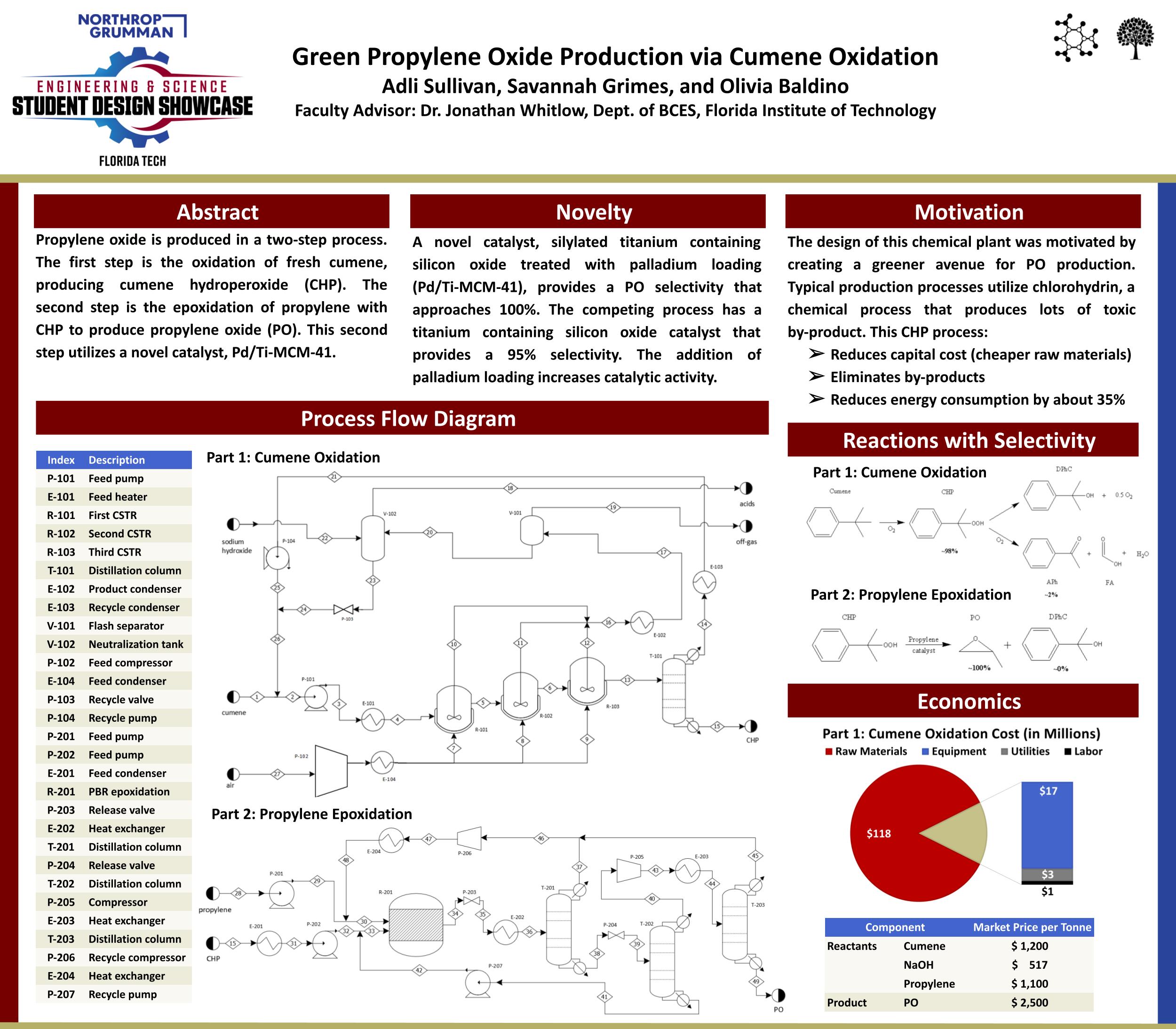
Our project encompasses the design of a chemical plant that produces propylene oxide in a two-step process. The first step is the auto-oxidation of fresh cumene, producing cumene hydroperoxide (CHP). The second step is the epoxidation of propylene with CHP to produce propylene oxide (PO). This second step utilizes a novel catalyst, silylated titanium containing silicon oxide treated with palladium loading (Pd/Ti-MCM-41), which provides a PO selectivity that approaches one hundred percent. This design was motivated by creating a greener avenue for PO production. Typical production processes utilize chlorohydrin, producing toxic by-products in a 40:1 ratio with the desired product. By using a peroxide, the harmful by-products are no longer an issue to be dealt with. There are four peroxides processes used for epoxidation, including the tert-butyl hydroperoxide process (PO/TBA), ethylbenzene hydroperoxide process (PO/SM), hydrogen peroxide process (HPPO), and cumene hydroperoxide process (PO/CHP). PO/CHP, as it is used in our process, provides for an elimination of by-products when the novel catalyst is used. PO/CHP is a relatively new process in the industry, but its benefits, both environmentally and economically, have proven themselves already. The combination of two processes, oxidation and epoxidation, into one continuous chemical plant process provided many challenges. The reactor configuration for cumene oxidation had to be modeled as 3 cascading CSTRs in our software, replacing the typical bubble column process used in industry. The exothermic nature of the cumene oxidation provided extra barriers, as many safety measures needed to be considered every step of the way to ensure the process did not produce a dangerous amount of heat or cause an explosion. Limits had to be placed on the reaction temperature and cumene conversion percentage. Fail-safe devices, such as cooling jackets and pressure vacuums, were introduced to the reactors, heat exchangers, and distillation column to get in front of any overheating that might occur. The market for PO is projected to increase due to the rising demand for polyurethanes. PO is a vital component in creating those polyether polyols required for the production of many plastics, resins, and elastomers. Polyurethanes are essential to the textile, automotive, and pharmaceutical industries. Ultimately, this process utilizes new green chemistry to produce a valuable intermediate, PO, while producing minimal by-products.Manufacturing Design Methods
Aspen Plus V12.1 software was used to simulate the cumene oxidation and propylene epoxidation processes. The simulation was optimized through sensitivity analyses that displayed the changes in specific process parameters when other parameters were varied. The generated values, such as selectivity, yield, and conversion, were compared to similar processes found in literature. The parameters of all equipment and feed streams, given by the simulation or pre-set, were used to perform a cost analysis.Sustainable Community
Team Leader(s)
Nathan DavisTeam Member(s)
Christian Perez, Gavin Olson, Nicholas Cannetti, Alexis Hensley, Austyn RueterFaculty Advisor
Troy NguyenSustainable Community File Download
Project Summary
As the population in Florida grows, the demand for housing is increasing. In today’s economic climate, the cost of housing is rapidly rising, making it more difficult for people to find housing. The purpose of this project is to help accommodate more affordable housing for the rising population in Florida. The goal of this project is to create energy-efficient and affordable housing for the public of Mims, Florida. One solution to the housing crisis while still providing privacy to the residents is to create a tiny housing community. The houses are around 600-800 square feet. Tiny houses provide an opportunity for people who wouldn't be able to afford a full-sized house to own their own property. These homes will also boast solar panels and modern materials in construction to reduce costs as much as possible.Project Objective
The goal of this project is to create energy-efficient and affordable housing for the public of Mims, Florida. One solution to the housing crisis while still providing privacy to the residents is to create a tiny housing community. Tiny houses provide an opportunity for people who wouldn't be able to afford a full-sized house to own their own property. These homes will also boast solar panels and modern materials in construction to reduce costs as much as possible.Manufacturing Design Methods
The Transportation Engineer designed all new roads and sidewalks in the community. We didn't have an architect on the team, so one of the Civil Engineers took responsibility for the architectural conceptual design of all three home floor layouts. Another Civil Engineer took on the job of Water Resources. They designed water systems, sanitary systems, and stormwater systems. Another Civil Engineer took on the geotechnical design of foundations for homes and roads based on existing soils.Specification
We used environmentally conscience materials to reduce our impact. Materials like Innova Panel MGO SIPs for walls and roofs and local RCA (recycled concrete aggregate) for subgrade. To make our community sustainable throughout its lifespan, we added the option to include 15kWh solar panels to the homes. There will be nine solar panels per Single and Multi-family home. The ADA home will have sixteen solar panels per home.Analysis
Cost for a single-bedroom home: $110,259.12 Cost for a two-bedroom home: $115,085.08 Cost for an ADA home: $122,672.52 An additional 20% will be added to these values above for overhead and profit. Total projected cost: $13,580,654.63 Total projected profit: $2,716,130.93 The construction schedule has been calculated and will take two years to build from start to finish. We used RS Means, a reference book that uses real-world data, to calculate the cost and schedule. Using Innova Panels we are able to expedite the build time significantly. Multiple units will be built simultaneously to reduce the project's overall schedule as well.Future Works
There are currently no plans for future works but expansion could be an option to assess at a future time.Other Information
Thank you for your time.Acknowledgement
Our team would like to acknowledge the facility advisors that helped guide us through this entire project.Automated Drone Navigation
Team Leader(s)
Michael GourdineTeam Member(s)
Chinedum Ajabor, Patrycja Bachleda, Richard DiazFaculty Advisor
Dr. Siddhartha BhattacharyyaSecondary Faculty Advisor
Parth GaneriwalaAutomated Drone Navigation File Download
Project Summary
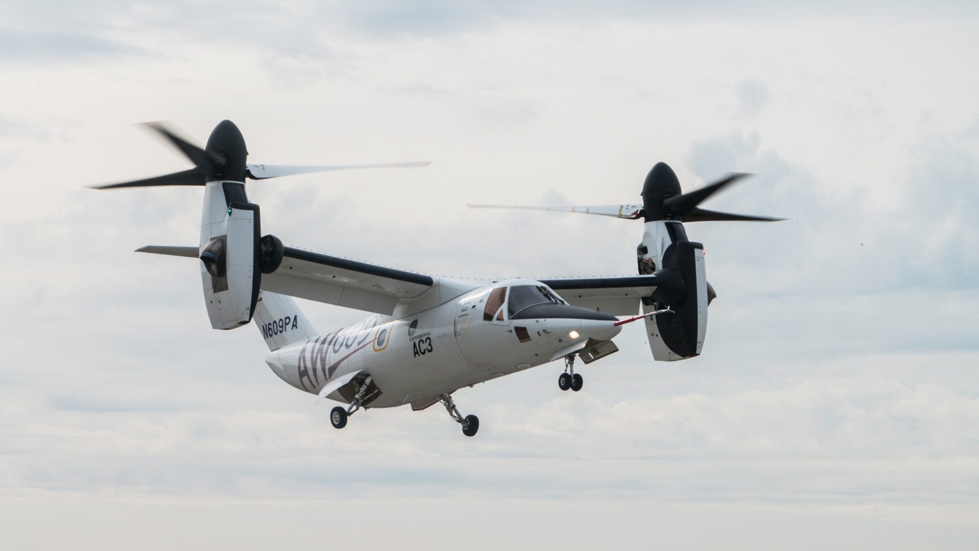
The Automated Drone Navigation project aims to mitigate the risks to public safety associated with the loss of communication between the aircraft AW609 and the command center. Through proper implementation of the SOAR cognitive architecture, we plan to develop an intelligent agent that can assume control of the AW609 during emergencies and navigate it back to its origin or destination safely, while avoiding densely populated areas. The project will also include a graphical user interface (GUI) for monitoring critical data such as fuel levels, airspeed, elevation, and altitude in real-time, as well as a map that tracks the aircraft's location and the path generated by the intelligent agent. Through these developments, the project seeks to ensure the safety of the public by having the agent navigate the AW609 around densely populated areas with minimized risk.Project Objective
Project Objective: The objective of this project is to mitigate the potential risks associated with operating the AW609 by implementing an automated system that permits the agent to assume control in situations where communication with the control tower is lost. By leveraging the SOAR cognitive architecture to design an intelligent agent capable of flying the aircraft to its intended destination or returning to the starting point during emergencies, we can guarantee the safety of the flight.Manufacturing Design Methods
Design: The system must be integrated with the SOAR architecture; a cognitive agent which performs decisions to pilot the aircraft in the XPlane 11 simulator. The aircraft under focus to be operated by the SOAR agent is the Agustawestland's AW609, which has a unique capability to takeoff/land vertically similarly to a helicopter and fly horizontally as a typical aircraft. This SOAR agent would be able to determine whether it must navigate, and land safety following proper FAA (Federal Aviation Agency) protocol. The SOAR agent would decide on the safest course of action to return back to its starting location or continue safely to its destination while avoid densely populated areas. Architecture challenges: The SOAR cognitive architecture, when implemented appropriately, is a general intelligent agent capable of performing tasks, learning, making decisions, solving problems, and planning based on information provided to it. This architecture is based on a platform that was quite novel to our team's methodology and took some time to get used to, as it requires proposals of certain rules that, when met, must be paired with a follow-on event execution. These proposals and events must then be chained in sequence to ensure the aircraft performs as expected. However, this required a lot of fine-tuning because the SOAR agent will always execute if the given conditions are met, even if the situation is not suited for that action, resulting in a paradigm shift in our team's thinking to perform countless system tests and make adjustments to the architecture. We were ultimately successful in creating an environment where the agent went from a 10% success rate in landings to 90%. Implementation Challenges: Upon activation of the loss of communication the SOAR agent would assume control of the aircraft and determine its current position relative to its initial position and compare it with a determined distance resulting from the pathfinding algorithm. The constraints of distance and fuel must be taken into account. The novelty of this project is the SOAR cognitive architecture deciding on the most appropriate course of action and fine tuning the algorithm has proven to be incredibly difficult. This implementation has caused us to revise our approach 3 separate times ultimately resulting in an amalgamation of Dijkstra and the on board AI system industrial aircrafts utilize. Previous attempts considered locations in the sparse regions of the map to have nodes and boundary nodes around densely populated areas shaping into an irregular polygon. The difficulty proved to be navigating as efficiently as possible without additional travel time and exceeding fuel constraints. The speed in which the Agent would have to determine which nodes to travers proved extensively difficult as each node required n^n total edges where n is the number of nodes. This proved to be incredibly overwhelming and as the aircraft was constantly moving, SOAR agent could not make a decisAnalysis
Analysis: Multiple tests were conducted to evaluate the decision-making capabilities of the agent in situations where communication is lost. Specifically, we developed numerous scenarios in which the aircraft was situated in densely populated areas following the loss of communication. The SOAR agent was expected to recognize the issue, identify the most efficient and direct flight path to escape the congested area and reach the intended destination, and proceed along that path until the destination was reached. Additionally, various other testing procedures were employed, including the placement of the aircraft in random locations and environmental conditions, to verify the agent's capacity to successfully initiate takeoff, operate the aircraft safely, and land it at the intended destination.Future Works
Future Works: Potential future developments for this project encompass incorporating machine learning to better predict path based on previous flight data, adding weather factors that may affect flight, and refining the SOAR architecture to improve the agent's decision-making process. Additionally, the optimization of the algorithm for flying around dense regions can be further enhanced to efficiently plot a course towards its destination.Other Information
However, it is important to note that all the testing were done in a simulated environment and do not account for the complexities of the actual aircraft, which would require further development and implementation.Electric Vehicle
Team Leader(s)
Thomas FrancisTeam Member(s)
Thomas Francis, Whitney Ellis, Arianna Issitt, Will Burk, Jonathan Kinkopf, Adrianna Agustin, Matthew Delgado, Mitchell Sales, Jiwoo Jeong, Bryce Fowler.Faculty Advisor
Lee CarawayProject Summary
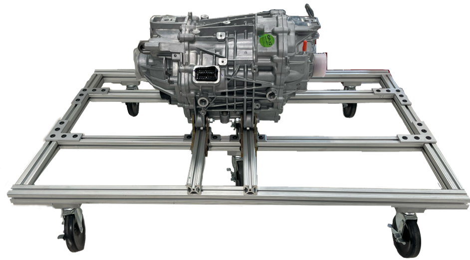
This project is tasked with the design and construction of a traction inverter for use in driving an electric motor. To do this, it will need to produce multiple systems that drive, process, and monitor different components within the construction. The project must create a supporting frame for the motor to rest and run on that is maneuverable and provides easy access to work on the electric motor. In order to drive the motor, a high and low voltage battery system must be designed for use by the motor, microprocessors, and MOSFETs. The microprocessors will interpret data from the motor and various components to monitor temperatures, read resolver data, and produce and interpret other necessary signals. To ensure safe operating conditions, temperatures for the MOSFETs and motor must be monitored and a cooling system developed for each.Analysis
The team decided to take on as many systems as possible. To do this, students were tasked with different elements in the system to research. Once adequate information was gathered, designs were conceptualized and reviewed to ensure the safety of students and components. Multiple subsystems were tested successfully, and simulations of the traction inverter circuit were developed.Future Works
The current proposal for this project is for future students to build on the foundation set by this year’s team and to carry on development towards a self-driving electric vehicle. This includes the continued maturing of the traction inverter system and its integration into the mechanical systems of an automobile, as well as the development of self-driving software.Testing the Relativistic-Microwave Theory of Ball Lightning with Plasma Simulations
Team Member(s)
Amanda ElliottFaculty Advisor
Dr. Vladislav Bukshtynov, Dept. of Mathematical Sciences, Florida TechTesting the Relativistic-Microwave Theory of Ball Lightning with Plasma Simulations File Download
Project Summary
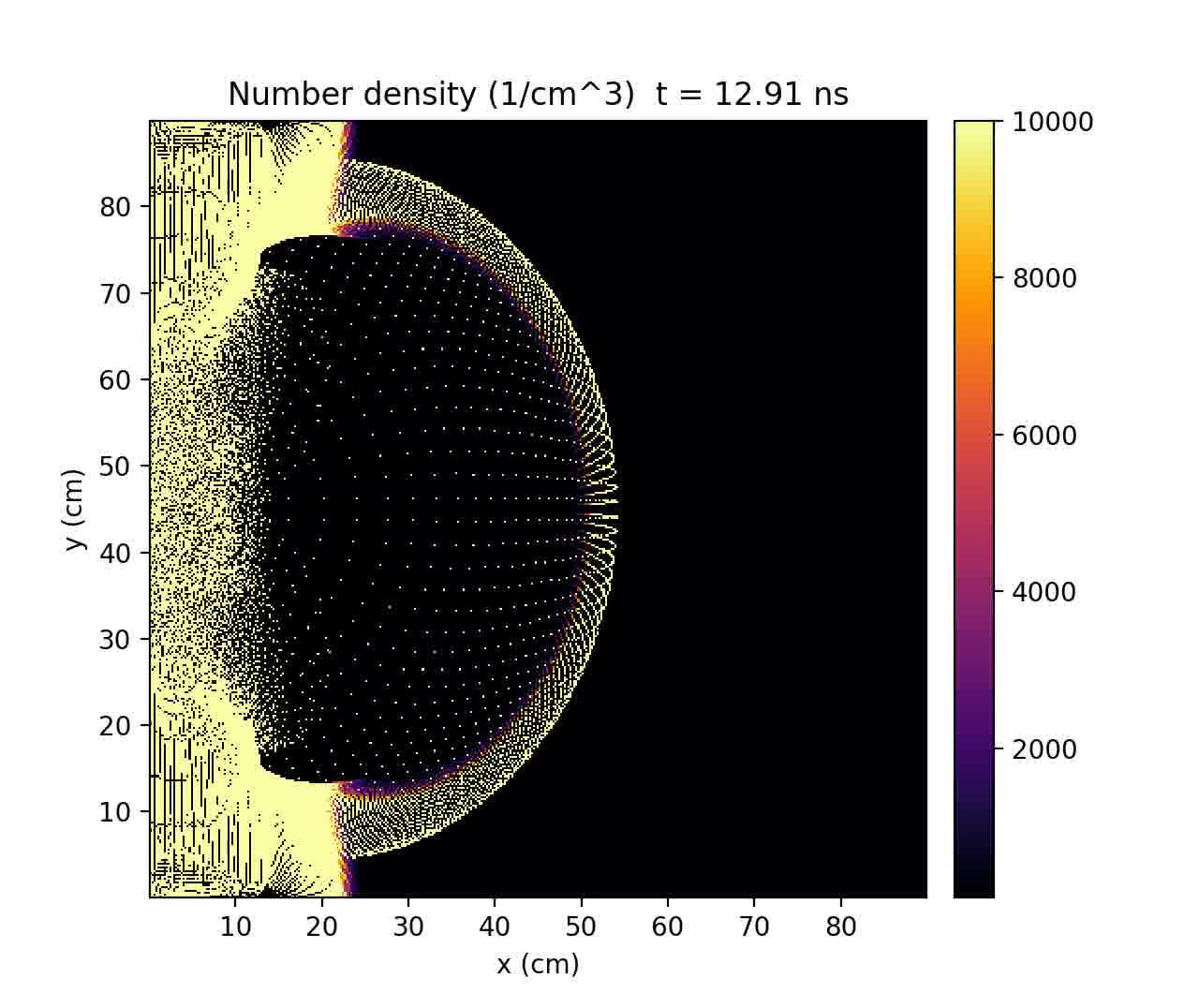
Ball lightning (BL) is an unexplained phenomenon reported by thousands of eyewitnesses as a fireball, a few cm to 1 m in diameter, moving unpredictably and independently of the wind, sometimes observed during lightning storms. Here a potential theory for the creation of BL is explored. BL objects are luminous, and so, must contain an energy source. It has been theorized that this energy source is a standing microwave that ionizes the air in a spherical shape. This theory is supported by the observation that the most common reported diameter for BL objects is in the same range as the wavelengths of microwaves. This plasma shell, or bubble, could contain the standing wave, but otherwise, would be a vacuum inside. This structure would also explain the two most commonly reported forms of termination of BL objects: (1) peaceful and (2) violent termination types. BL objects have been observed to terminate by either (1) dissipating silently like a gas, or (2) to explode with a violent burst of energy that has been lethal. These two termination types suggest that BL object stability is analogous to that of a bubble, and is highly dependent on the balance of internal and external pressure and surface tension. The goal of this project is to replicate previously simulated results (by researcher Hui-Chun Wu) that suggest a way for this theorized BL structure to be created at the end of a lightning strike. The open-source Particle-in-Cell (PIC) code called Smilei is used to simulate plasma in a 2D environment. These BL creation results are divided into two separate simulations. For the first simulation, the conditions are simulated at the end of a lightning leader approaching the ground. The resulting strong electric field could lead to an electron bunch with an of energy of 50 MeV, in the relativistic rang. This electron bunch is accelerated by the field toward ground, modeled as conductor, or overdense plasma. This resulted in a radial pulse of coherent transition radiation (CTR), which is the hypothetical energy source for a BL object. This CTR was successfully simulated to have a magnitude of 317 MV/m, which is close to the Wu's original simulated value of ~310 MV/m. The goal for the second simulation is to model the standing wave trapping in a spherical plasma “bubble.” For this simulation, an input standing wave pulse is modeled using a sine wave traveling within a Gaussian envelope. For this simulation, the plasma shell forms, but expands outward without stabilizing. The original results that were partially replicated here were generated by Wu’s personal PIC code and may not be reproducible using standard PIC codes that are designed for vacuum. Atmospheric molecule collisions with electrons cannot be simulated at this time scale, but the resulting energy loss can be approximated and may stabilize the plasma shell. Once a successful theory and corresponding simulation of BL creation is achieved, this will inform how to generate BL in a laboratory or during thunderstorms. The results of this research will advance lightning protection, aviation safety, and broaden our knowledge of plasma physics and confinement methods.Project Objective
The goal of this project is to replicate previously simulated results that suggest a way for this theorized BL structure to be created at the end of a lightning strike. The open-source Particle-in-Cell (PIC) code called Smilei is used to simulate plasma in a 2D environment. These BL creation results are divided into two separate simulations.Analysis
Particle-in-Cell (PIC) codes are commonly used for plasma simulations. They operate by initializing charged particles to a spatial grid, and calculating the resulting electromagnetic fields using a Maxwell solver. They then calculate new particle positions and velocities based on Newtonian equations of motion. The PIC code selected for this project is an open-source code called Smilei. It contains the above features that are characteristic of PIC codes, but also includes relativistic effects and solves the Vlasov-Maxwell equation for collisionless plasmas. Inherent in Smilei's equations of motion is the radiation pressure, or ponderomotive, force which is vital for simulating the plasma bubble formation.Future Works
Improvements for the second simulation is ongoing. The simulation assumed vacuum conditions, and so the next step is to approximate the energy loss that electrons experience when colliding with air molecules, and apply this to the simulation. Once this is accomplished, the results can be compared with Wu's, and this theory for BL creation can be evaluated. There are ideas to expand this model to explain additional properties of BL objects. The goal is to develop a comprehensive model that explains BL creation, its stability during its lifespan, and the two most common forms of termination.Acknowledgement
Dr. Jean C. Perez for his stellar plasma physics education.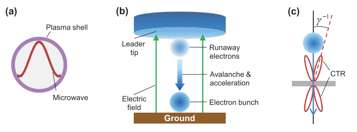
PLA-S-TECH: PLA Sustainable Technology
Team Leader(s)
Sean SapperTeam Member(s)
Ryan DeCarlo, Elliot Whitney, Samantha Dombrowski, Dalton Prokop, Dominic Zaio, Tyler Stokes, David Deese, Blake Hengel, Yi GuoFaculty Advisor
Dr. Douglas E. WillardPLA-S-TECH: PLA Sustainable Technology File Download
Project Summary
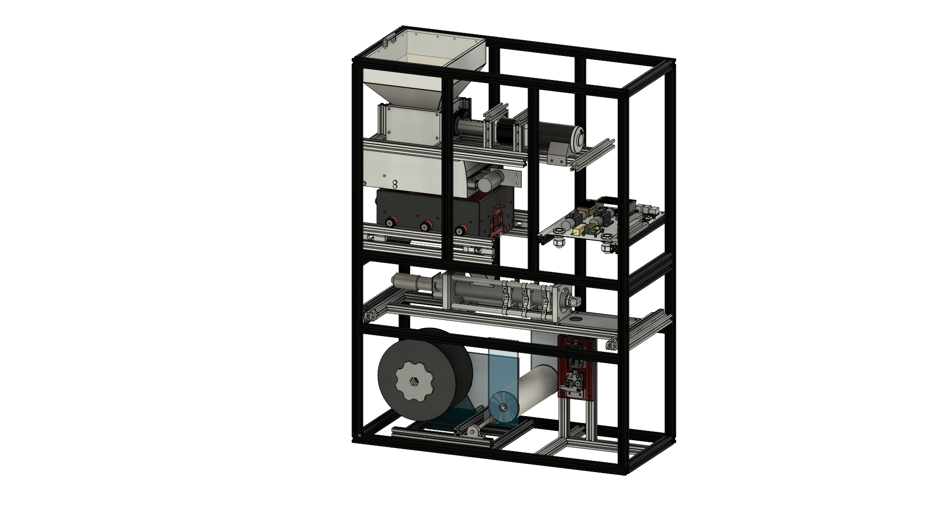
The L3HSDC requested a machine capable of recycling its large amount of scrap PLA plastic into reusable filament for their 3D printers. Our team was tasked with designing, building, and testing this recycling machine, which needed to break down the plastic into small pieces, melt those pieces into a molten state, extrude the melted plastic into filament, and wrap it onto a standard filament spool. In order to accomplish this, the project was divided into three main subsystems: Reducer, Producer, and Automation and Controls. The Reducer consists of all components integral to the breaking down, filtering, and storing of the plastic. The Producer consists of all components integral to melting, extruding, checking diameter, and spooling the plastic. Automation and Controls ties all components together by controlling electronics and mechanical assemblies, as well as constantly monitoring safety parameters.Project Objective
This recycling machine must take the customer’s discarded PLA plastic as input and output recycled PLA filament. To accomplish this, the plastic is shredded into very small pieces for uniform melting. The shredded plastic then enters a filtering mechanism before being held in a storage container. Upon process start, the small plastic pieces are fed into the extrusion mechanism, similar to injection molding technology, which melts down the solid plastic pieces into molten PLA. Once melted fully, the plastic is compressed and extruded as a continuous strand of recycled filament. This new filament is then measured to ensure the diameter is the same as the standard diameter for 3D printing filament. Finally, the recycled filament is wrapped onto a standard 3D printing spool via the spooling mechanism. The recycling machine is designed to be composed primarily of commercially available parts to ensure that the customer has little to no issues when finding replacements for worn or damaged components. Due to the dangerous nature of this machine and its various mechanisms, there are numerous safety barriers in place to ensure user safety while the machine is active. There are also safety parameters that continuously check data against nominal values in order to catch any system irregularities, such as overheating or motor malfunction. Additionally, the team is providing the customer with an operation manual, which includes safety guidelines, as well as a maintenance plan outlining the required service the product will need to ensure maximum safety, efficiency, and longevity when operating.Manufacturing Design Methods
The largest challenge faced during the design and manufacturing of the recycler was attempting to create prototypes early in the design process. The goal of this was to address any design flaws that may have presented themselves, as well as to have more time if it was necessary to pursue a whole new design approach. Using heat analysis and static structural analysis in both Fusion 360 and ANSYS Workbench were essential when ensuring our designs were fully informed. Iterative design was the key to this project, as the CAD models for each of the core components of the machine were continually updated and improved upon until the final designs were solidified. However, this meant the design stage lasted longer than scheduled, which proved detrimental to our progress over time. Manufacturing for this project consisted primarily of using the water jet machine to cut out metal parts. Many parts for our Producer components were machined by hand or using the CNC mill. Any other parts that were custom designed were made using 3D printers. Prototypes in the early stage of the project also used 3D printed parts, as well as wood and acrylic parts cut on the large-format laser cutters.Specification
Weight: ~150 lb. Size: 0.70m W x 0.94m H x 0.30m D (27.6" W x 37.0" H x 11.8" D) Storage capabilities: up to 2.5 kg of shredded PLA Process time (1 kg):Analysis
Heat analysis and static structural analysis in both Fusion 360 and ANSYS Workbench were used when designing most parts due to the high temperatures inside a section of the machine. Calculations were done by hand as well as in Excel to determine torque and force in the shredder mechanism, as well as when determining rotation and translation speeds for the spooling mechanism.Future Works
In the future, the final design for our machine could be improved upon as it is used in the L3Harris Student Design Center. Troubleshooting opportunities may arise that could require some redesigning of parts or slight modifications to system function.Acknowledgement
Thank you to the L3Harris Student Design Center and Peter Zappala, as well as our GSA, Ethan Bair, for supporting this project and our team.R3MORA
Team Leader(s)
Parker BaillonTeam Member(s)
Suzie Dixon, Katlynd Faust, Payton Herman, Harpoon SeabringFaculty Advisor
Dr. Stephen WoodSecondary Faculty Advisor
Dr. Ronnal ReichardR3MORA File Download
Project Summary
Project R3MORA (Resin 3D Printed Marine Operable Research Assistant) is a multi-stage project. The first portion of this project developed a complete set of material properties for three different Siraya Tech Stereolithography (SLA) 3D printing resins. This portion of the project was published at the Ocean Hampton Roads Conference 2022 and was well received. Printing pressure enclosures greatly reduces cost and creates many possibilities for customization. Based on the data and techniques published, many parties have shown interest in adopting the process for low-cost student design competitions. In addition to the competition groups, the resin pressure enclosures are also being utilized for biofouling control testing at Port Canaveral. The second portion designed and produced a small, diver-deployable, remotely-operated vehicle (ROV) printed using the materials tested during stage one. A variety of goals can be completed with the R3MORA vehicle, and many of them apply to the average recreational diver. Using R3MORA, divers who are not certified for cave exploration or internal spaces in shipwrecks, for example, may gain access to these places that they normally could not explore. Divers who operate the R3MORA also increase their access to unique footage or photography capabilities. Furthermore, the R3MORA vehicle can increase the general safety of the diver as it would provide situational awareness through the video stream. It could also be utilized to help locate a missing diver or item in an unsafe situation. It would fill a public safety niche within the diving community, thus having a positive societal impact.Project Objective
1) Develop a set of ASTM material properties for Siraya Tech SLA 3D printed resins. 2) Design a 3D-printed pressure enclosure for a small, diver-deployable ROV. 3) Design and build a functional prototype of the diver-deployable ROVManufacturing Design Methods
Project R3MORA was manufactured from all 3D printed parts. This kept costs low and allows the project to be open source so the barrier to entry to an ROV can now be greatly reduced.Specification
Depth Rating: 400ft Endurance: 2hrs Sensors: Temperature and Depth HD Camera Modular expansion ports 6 Motors 6 Degree of FreedomAnalysis
Design work was completed with Fusion 360. The built-in NASTRAN FEA solver was used for the analysis of the pressure enclosures. Material testing data from the Universal Testing Machine was processed with MATLAB.Future Works
Publication of Vehicle Design paper in Oceans 2023 Conference Mississippi Development of Underwater controller and tether management system Testing of long-term exposure of pressure enclosures for other oceanographic projectsAcknowledgement
We would like to thank all those involved in the Underwater Technology Lab, Structural Composites, Inc., and the Center for Corrosion and Biofouling Control for continuously lending their knowledge and support. Without any of the parties listed above R3MORA would not have been possible.Exploring the Role of the Diurnal Cycle of Solar Radiation on Precipitation Over the Maritime Continent
Team Member(s)
Jenelle EdwardsFaculty Advisor
Pallav RayExploring the Role of the Diurnal Cycle of Solar Radiation on Precipitation Over the Maritime Continent File Download
Project Summary
The MJO is a global oscillation that occurs on a sub-seasonal timescale and is best known for its deep convection and propagation through the Maritime Continent (MC). Due to the numerous variables that can impact the propagation of the MJO through the MC, including the atmospheric moisture, winds, and topography, predicting the patterns of the MJO proves to be difficult for models. This study looks at how the diurnal cycle of solar radiation and background wind patterns impact the MJO precipitation across the MC and for each of the 3 major islands. The diurnal cycle of solar radiation had the tendency to produce more rain than the simulation with no diurnal cycle. By analyzing the wind patterns over the total time period, it was able to be determined that times where there were westerly winds produced more precipitation than the easterly winds.Electrostatic Dust Lofting: A Possible Cause for Beam Losses at CERN’s LHC

Team Member(s)
Amanda ElliottFaculty Advisor
Dr. Paul MartinSecondary Faculty Advisor
Dr. Hamid K. RassoulElectrostatic Dust Lofting: A Possible Cause for Beam Losses at CERN’s LHC File Download
Project Summary
Dust particles interacting with the proton beams have caused thousands of beam-loss events at CERN’s Large Hadron Collider (LHC), some of which led to premature beam dumps and even magnet quenches, frequently resulting in day-long shutdowns. It has been hypothesized that dust particles on the vacuum chamber wall of the LHC become negatively charged due to electron clouds and can detach from the chamber wall by the electric field of the beam. To test this hypothesis, we performed experiments in a vacuum chamber to study the electrostatic lofting of dust particles from conducting surfaces. First, a monolayer of dust (silica,Project Objective
To test this hypothesis, we designed and performed experiments in a vacuum chamber to study the electrostatic lofting of dust particles from a conducting surface. Dust charging and high voltage lofting experiments are performed, and the resulting dust movement is recorded using a high-speed camera. The properties of dust charging and levitation are characterized from these videos. In order to achieve the long-term goal of dust mitigation in the LHC, we must first understand the relevant parameters that facilitate dust lofting.Analysis
The properties of dust charging and levitation are characterized from recorded high-speed videos. Scripts were developed to process these videos. The common algorithms for these scripts include lofted particle detection, multiple particle tracking, size calculation using a Flood Fill algorithm, particle velocity and acceleration calculations, and correction for the camera angle relative to the dust sample. Different calculations are performed depending on whether the dust grains lofted during high voltage (vertical trajectories) or during charging (parabolic trajectories). Additional calculations are performed for dust grain surface potential, charge, and lofted angle using QR Factorization.Future Works
Experiments are ongoing at the University of Colorado, Boulder, with the goal of better replicating LHC conditions using sudden impulse charging and high voltage application. It is also important to note that dust in the LHC experiences charging (from synchrotron radiation) and high voltage simultaneously, while we have only tested charging and high voltage applications separately. Data has been collected from charging using an UV lamp and high voltage application simultaneously, and is in the process of being analyzed.Other Information
This research is being presented at a poster session at the International Particle Accelerator Conference (IPAC) in Venice, Italy on May 7-12, 2023, by one of our CERN collaborator's, Rudiger Schmidt.Acknowledgement
Experiments are performed under the advisement of Xu Wang and Mihály Horányi at the Institute for Modeling Plasma, Atmospheres, and Cosmic Dust (IMPACT), at the University of Colorado, Boulder. This project is an ongoing collaboration with the following CERN researchers: Rudiger Schmidt, Daniel Wollmann, Christoph Wiesner, and Philippe Belanger. This research was funded by NSF’s physics Research Experience for Undergraduates (REU) program.Ordinance Development, Grant Writing, and Outreach to Advance Sustainability in the Town of Melbourne Beach, FL

Team Member(s)
Reese JohnsonFaculty Advisor
Dr. Ken Lindeman, Dept. Of Ocean Engineering, Florida Institute of TechnologyOrdinance Development, Grant Writing, and Outreach to Advance Sustainability in the Town of Melbourne Beach, FL File Download